3 timer 1, Figure 25 – Rainbow Electronics T89C51AC2 User Manual
Page 53
53
T89C51AC2
Rev. B – 19-Dec-01
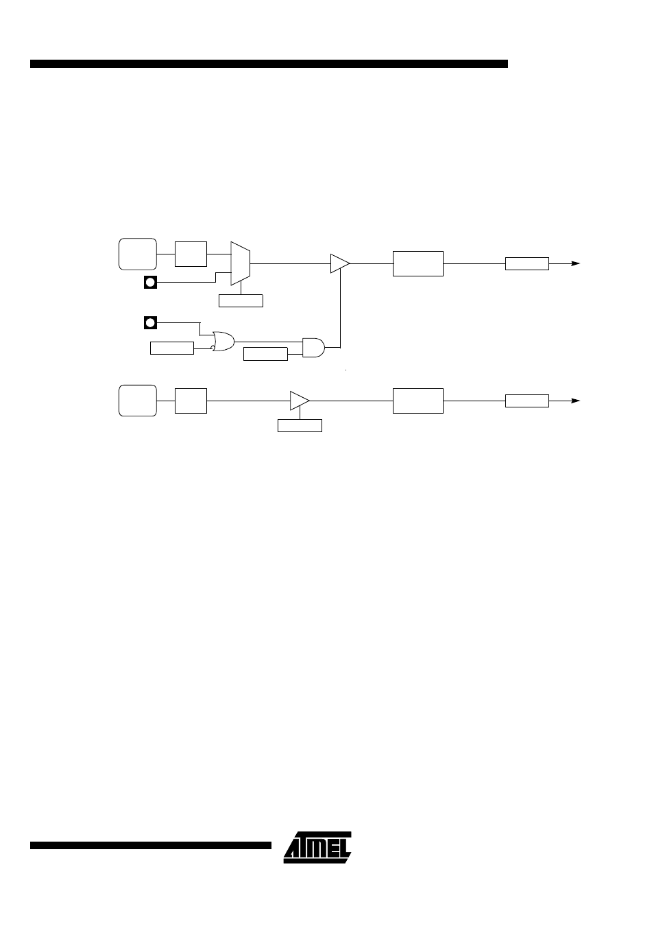
12.2.4 Mode 3 (Two 8-bit
Timers)
Mode 3 configures Timer 0 such that registers TL0 and TH0 operate as separate 8-bit
Timers (see Figure 25). This mode is provided for applications requiring an additional 8-
bit Timer or Counter. TL0 uses the Timer 0 control bits C/T0# and GATE0 in TMOD reg-
ister, and TR0 and TF0 in TCON register in the normal manner. TH0 is locked into a
Timer function (counting F
PER
/6) and takes over use of the Timer 1 interrupt (TF1) and
run control (TR1) bits. Thus, operation of Timer 1 is restricted when Timer 0 is in mode
3.
Figure 25. Timer/Counter 0 in Mode 3: Two 8-bit Counters
12.3 Timer 1
Timer 1 is identical to Timer 0 excepted for Mode 3 which is a hold-count mode. Follow-
ing comments help to understand the differences:
•
Timer 1 functions as either a Timer or event Counter in three modes of operation.
Figure 22 to Figure 24 show the logical configuration for modes 0, 1, and 2. Timer
1’s mode 3 is a hold-count mode.
•
Timer 1 is controlled by the four high-order bits of TMOD register (see Figure 21)
and bits 2, 3, 6 and 7 of TCON register (see Figure 20). TMOD register selects the
method of Timer gating (GATE1), Timer or Counter operation (C/T1#) and mode of
operation (M11 and M01). TCON register provides Timer 1 control functions:
overflow flag (TF1), run control bit (TR1), interrupt flag (IE1) and interrupt type
control bit (IT1).
•
Timer 1 can serve as the Baud Rate Generator for the Serial Port. Mode 2 is best
suited for this purpose.
•
For normal Timer operation (GATE1= 0), setting TR1 allows TL1 to be incremented
by the selected input. Setting GATE1 and TR1 allows external pin INT1# to control
Timer operation.
•
Timer 1 overflow (count rolls over from all 1s to all 0s) sets the TF1 flag generating
an interrupt request.
•
When Timer 0 is in mode 3, it uses Timer 1’s overflow flag (TF1) and run control bit
(TR1). For this situation, use Timer 1 only for applications that do not require an
interrupt (such as a Baud Rate Generator for the Serial Port) and switch Timer 1 in
and out of mode 3 to turn it off and on.
•
It is important to stop Timer/Counter before changing mode.
TR0
TCON.4
TF0
TCON.5
INT0#
0
1
GATE0
TMOD.3
Overflow
Timer 0
Interrupt
Request
C/T0#
TMOD.2
TL0
(8 bits)
TR1
TCON.6
TH0
(8 bits)
TF1
TCON.7
Overflow
Timer 1
Interrupt
Request
T0
FTx
CLOCK
÷
6
FTx
CLOCK
÷
6
see section “Clock”