Rainbow Electronics T89C51AC2 User Manual
Page 5
5
T89C51AC2
Rev. B – 19-Dec-01
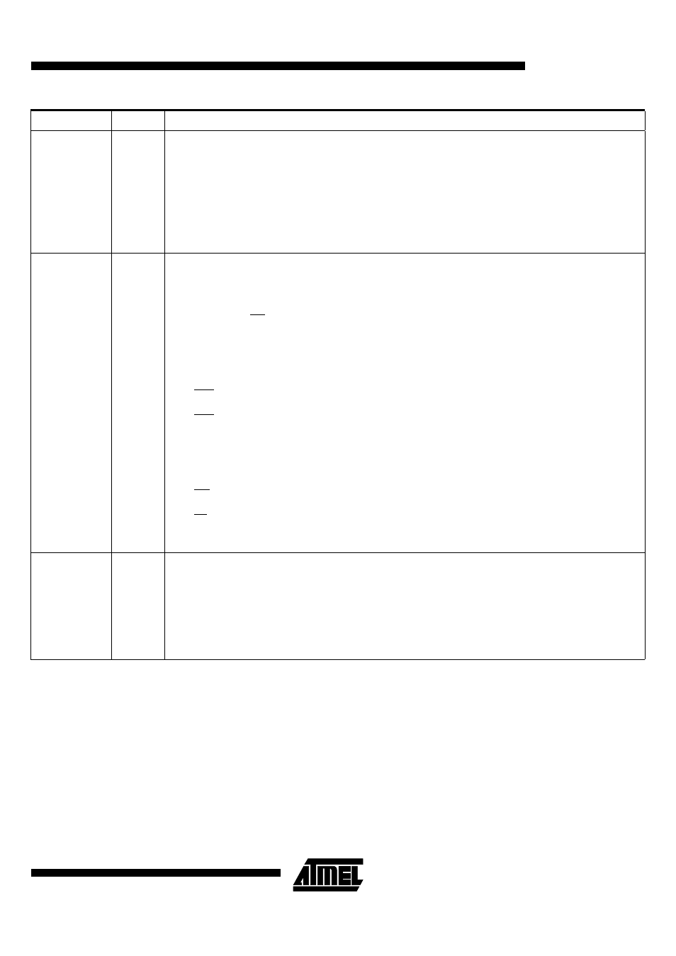
P2.0:7
I/O
Port 2:
Is an 8-bit bi-directional I/O port with internal pull-ups. Port 2 pins that have 1’s written to them are pulled high by the
internal pull-ups and can be used as inputs in this state. As inputs, Port 2 pins that are being pulled low externally will
be a source of current (I
IL
, see section "Electrical Characteristic") because of the internal pull-ups. Port 2 emits the
high-order address byte during accesses to the external Program Memory and during accesses to external Data
Memory that uses 16-bit addresses (MOVX @DPTR). In this application, it uses strong internal pull-ups when emitting
1’s. During accesses to external Data Memory that use 8 bit addresses (MOVX @Ri), Port 2 transmits the contents of
the P2 special function register.
It also receives high-order addresses and control signals during program validation.
It can drive CMOS inputs without external pull-ups.
P3.0:7
I/O
Port 3:
Is an 8-bit bi-directional I/O port with internal pull-ups. Port 3 pins that have 1’s written to them are pulled high by the
internal pull-up transistors and can be used as inputs in this state. As inputs, Port 3 pins that are being pulled low
externally will be a source of current (I
IL
, see section "Electrical Characteristic") because of the internal pull-ups.
The output latch corresponding to a secondary function must be programmed to one for that function to operate
(except for TxD and WR). The secondary functions are assigned to the pins of port 3 as follows:
P3.0 / RxD:
Receiver data input (asynchronous) or data input/output (synchronous) of the serial interface
P3.1 / TxD:
Transmitter data output (asynchronous) or clock output (synchronous) of the serial interface
P3.2 / INT0:
External interrupt 0 input / timer 0 gate control input
P3.3 / INT1:
External interrupt 1 input / timer 1 gate control input
P3.4 / T0:
Timer 0 counter input
P3.5 / T1:
Timer 1 counter input
P3.6 / WR:
External Data Memory write strobe; latches the data byte from port 0 into the external data memory
P3.7 / RD:
External Data Memory read strobe; Enables the external data memory.
It can drive CMOS inputs without external pull-ups.
P4.0:1
I/O
Port 4:
Is an 2-bit bi-directional I/O port with internal pull-ups. Port 4 pins that have 1’s written to them are pulled high by the
internal pull-ups and can be used as inputs in this state. As inputs, Port 4 pins that are being pulled low externally will
be a source of current (IIL, on the datasheet) because of the internal pull-up transistor.
P4.0
P4.1:
It can drive CMOS inputs without external pull-ups.
Pin Name
Type
Description