Serial i/o port, 1 framing error detection – Rainbow Electronics T89C51AC2 User Manual
Page 45
45
T89C51AC2
Rev. B – 19-Dec-01
11. Serial I/O Port
The T89C51AC2 I/O serial port is compatible with the I/O serial port in the 80C52.
It provides both synchronous and asynchronous communication modes. It operates as a
Universal Asynchronous Receiver and Transmitter (UART) in three full-duplex modes
(Modes 1, 2 and 3). Asynchronous transmission and reception can occur simultaneously
and at different baud rates
Serial I/O port includes the following enhancements:
•
Framing error detection
•
Automatic address recognition
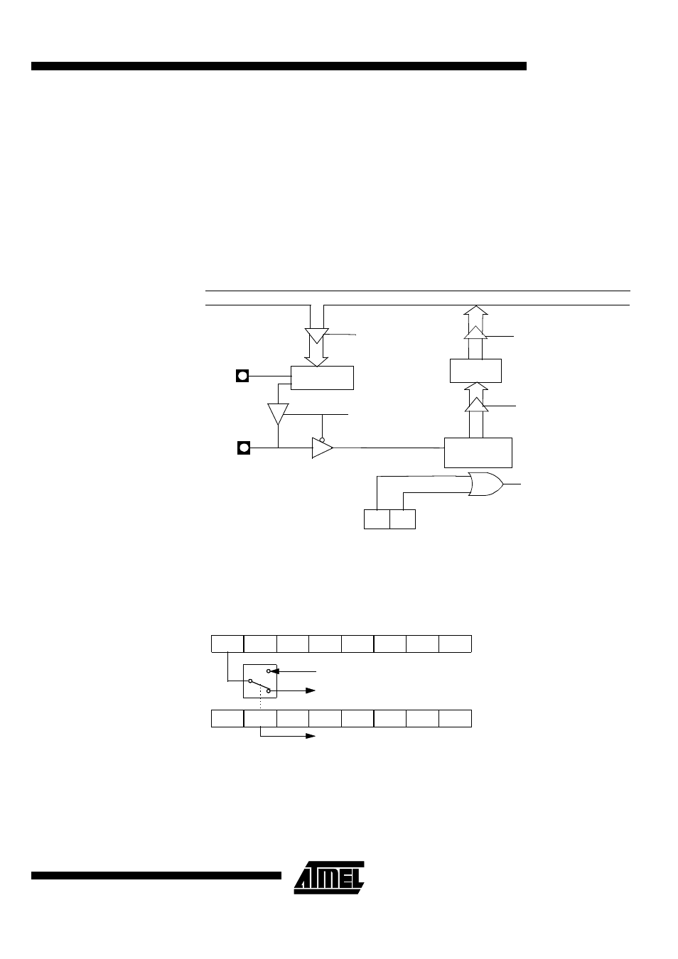
Figure 18. Serial I/O Port Block Diagram
11.1 Framing Error
Detection
Framing bit error detection is provided for the three asynchronous modes. To enable the
framing bit error detection feature, set SMOD0 bit in PCON register.
Figure 19. Framing Error Block Diagram
When this feature is enabled, the receiver checks each incoming data frame for a valid
stop bit. An invalid stop bit may result from noise on the serial lines or from simultaneous
transmission by two CPUs. If a valid stop bit is not found, the Framing Error bit (FE) in
SCON register bit is set.
The software may examine the FE bit after each reception to check for data errors.
Once set, only software or a reset clears the FE bit. Subsequently received frames with
Write SBUF
RI
TI
SBUF
Transmitter
SBUF
Receiver
IB Bus
Mode 0 Transmit
Receive
Shift register
Load SBUF
Read SBUF
Interrupt
Request
Serial Port
TXD
RXD
RI
TI
RB8
TB8
REN
SM2
SM1
SM0/FE
IDL
PD
GF0
GF1
POF
-
SMOD0
SMOD1
To UART framing error control
SM0 to UART mode control
Set FE bit if stop bit is 0 (framing error)