Programmable counter array pca, 1 pca timer – Rainbow Electronics T89C51AC2 User Manual
Page 69
69
T89C51AC2
Rev. B – 19-Dec-01
15. Programmable
Counter Array PCA
The PCA provides more timing capabilities with less CPU intervention than the standard
timer/counters. Its advantages include reduced software overhead and improved accu-
racy. The PCA consists of a dedicated timer/counter which serves as the time base for
an array of five compare/capture modules. Its clock input can be programmed to count
any of the following signals:
•
PCA clock frequency / 6 (see “clock” section)
•
PCA clock frequency / 2
•
Timer 0 overflow
•
External input on ECI (P1.2)
Each compare/capture modules can be programmed in any one of the following modes:
•
rising and/or falling edge capture,
•
software timer,
•
high-speed output,
•
pulse width modulator.
Module 4 can also be programmed as a watchdog timer. see Section "PCA Watchdog
Timer".
When the compare/capture modules are programmed in capture mode, software timer,
or high speed output mode, an interrupt can be generated when the module executes its
function. All five modules plus the PCA timer overflow share one interrupt vector.
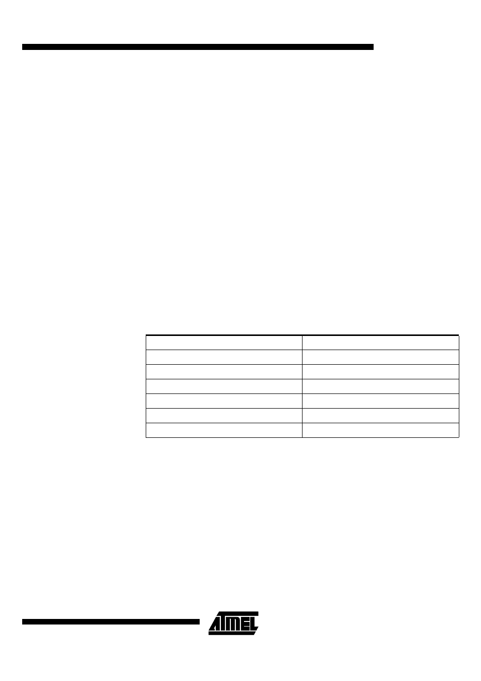
The PCA timer/counter and compare/capture modules share Port 1 for external I/Os.
These pins are listed below. If the port is not used for the PCA, it can still be used for
standard I/O.
15.1 PCA Timer
The PCA timer is a common time base for all five modules (see Figure 30). The timer
count source is determined from the CPS1 and CPS0 bits in the CMOD SFR (see Table
8) and can be programmed to run at:
•
1/6 the PCA clock frequency.
•
1/2 the PCA clock frequency.
•
the Timer 0 overflow.
•
the input on the ECI pin (P1.2).
PCA component
External I/O Pin
16-bit Counter
P1.2 / ECI
16-bit Module 0
P1.3 / CEX0
16-bit Module 1
P1.4 / CEX1
16-bit Module 2
P1.5 / CEX2
16-bit Module 3
P1.6 / CEX3
16-bit Module 4
P1.7 / CEX4