2 register, Table 12, Figure 6 – Rainbow Electronics T89C51AC2 User Manual
Page 17
17
T89C51AC2
Rev. B – 19-Dec-01
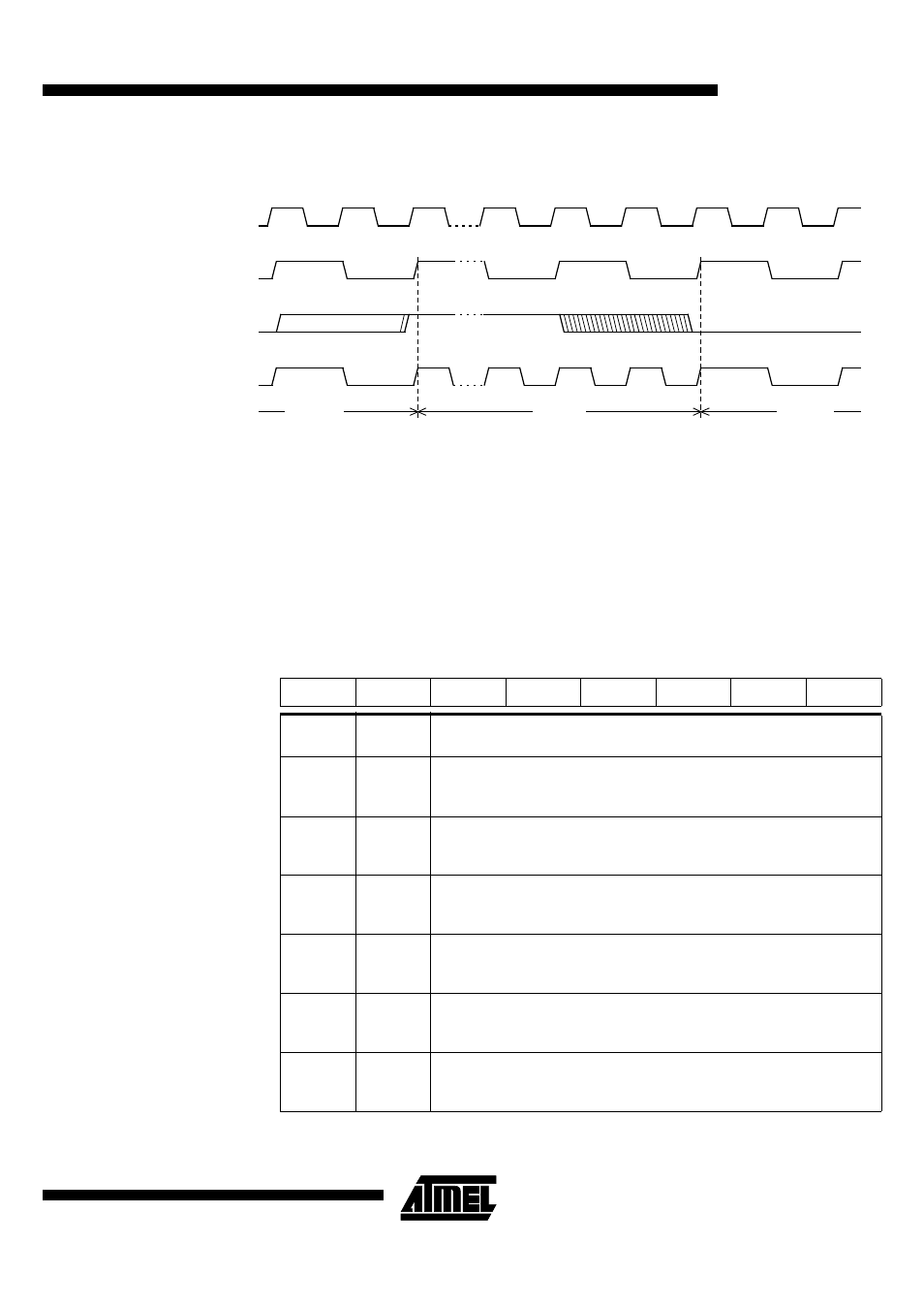
Figure 6. Mode Switching Waveforms
Note:
In order to prevent any incorrect operation while operating in the X2 mode, users must be
aware that all peripherals using the clock frequency as a time reference (UART, timers...)
will have their time reference divided by two. For example a free running timer generating
an interrupt every 20 ms will then generate an interrupt every 10 ms. A UART with a
4800 baud rate will have a 9600 baud rate.
6.2 Register
Table 12. CKCON Register
CKCON (S:8Fh)
Clock Control Register
XTAL2
XTAL1
CPU clock
X2 bit
X2 Mode
STD Mode
STD Mode
7
6
5
4
3
2
1
0
-
WDX2
PCAX2
SIX2
T2X2
T1X2
T0X2
X2
Bit
Number
Bit
Mnemonic
Description
6
WDX2
Watchdog clock (1)
Clear to select 6 clock periods per peripheral clock cycle.
Set to select 12 clock periods per peripheral clock cycle.
5
PCAX2
Programmable Counter Array clock (1)
Clear to select 6 clock periods per peripheral clock cycle.
Set to select 12 clock periods per peripheral clock cycle.
4
SIX2
Enhanced UART clock (MODE 0 and 2) (1)
Clear to select 6 clock periods per peripheral clock cycle.
Set to select 12 clock periods per peripheral clock cycle.
3
T2X2
Timer2 clock (1)
Clear to select 6 clock periods per peripheral clock cycle.
Set to select 12 clock periods per peripheral clock cycle.
2
T1X2
Timer1 clock (1)
Clear to select 6 clock periods per peripheral clock cycle.
Set to select 12 clock periods per peripheral clock cycle.
1
T0X2
Timer0 clock (1)
Clear to select 6 clock periods per peripheral clock cycle.
Set to select 12 clock periods per peripheral clock cycle.