Combination mode 3: manchester modulation 1, Combination mode 4: manchester modulation 2, Figure 76 – Rainbow Electronics T48C862-R4 User Manual
Page 80: Figure 77
80
T48C862-R4
4551B–4BMCU–02/03
Combination Mode 3:
Manchester Modulation 1
SSI mode 1:
8-bit shift register internal data output (SO) to the Timer 2
modulator stage
Timer 2 mode 1, 2, 3 or 4:
8-bit compare counter with 4-bit programmable prescaler
Timer 2 output mode 5:
The modulator 2 of Timer 2 modulates the SSI internal
data output to Manchester code
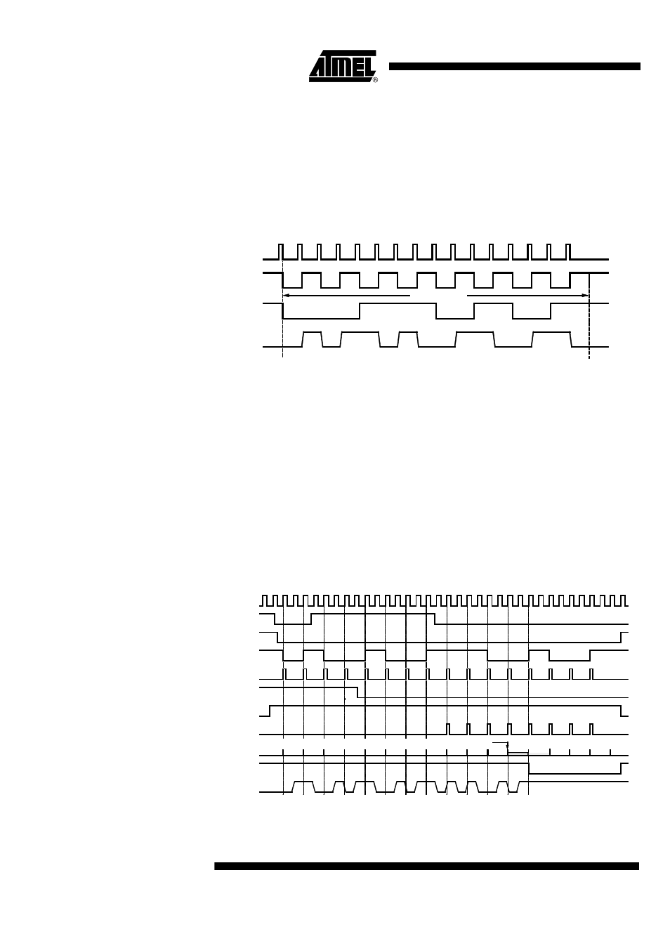
Figure 76.
Manchester Modulation 1
Combination Mode 4:
Manchester Modulation 2
SSI mode 1:
8-bit shift register internal data output (SO) to the Timer 2
modulator stage
Timer 2 mode 3:
8-bit compare counter and 4-bit prescaler
Timer 2 output mode 5:
The modulator 2 of Timer 2 modulates the SSI data output
to Manchester code
The 4-bit stage can be used as prescaler for the SSI to generate the stop signal for mod-
ulator 2. The SSI has a special mode to supply the prescaler with the shift clock.
The control output signal (OMSK) of the SSI is used as stop signal for the modulator.
Figure 72 shows an example for a 12-bit Manchester telegram.
Figure 77.
Manchester Modulation 2
TOG2
SC
SO
T2O
0
0
0
0
0
1
1
0
1
0
1
1
1
1
1
8-bit SR-data
Bit 7
Bit 0
0
Bit 7
Bit 0
Data: 00110101
0
0
0
0
0
0
0
0
1
2
3
4
0
1
2
0
Counter 2/1 = Compare Register 2/1 (= 4)
Bit 7 Bit 6
Bit 5 Bit 4 Bit 3 Bit 2 Bit 1 Bit 0 Bit 7 Bit 6 Bit 5 Bit 4 Bit 3 Bit 2 Bit 1 Bit 0
SCLI
Buffer full
SIR
SO
SC
MSM
Timer 2
Mode 3
SCL
Counter 2/1
OMSK
T2O
3