Electrical characteristics (continued) – Rainbow Electronics MAX17008 User Manual
Page 7
MAX17007A/MAX17008
Dual and Combinable QPWM Graphics
Core Controllers for Notebook Computers
_______________________________________________________________________________________
7
Note 1: On-time and off-time specifications are measured from 50% point to 50% point at the DH pin with LX = GND, V
BST
= 5V, and
a 250pF capacitor connected from DH to LX. Actual in-circuit times might differ due to MOSFET switching speeds.
Note 2: The 0 to 0.5V range is guaranteed by design, not production tested.
Note 3: Not production tested.
Note 4: Specifications at T
A
= -40°C to +105°C are guaranteed by design, not production tested.
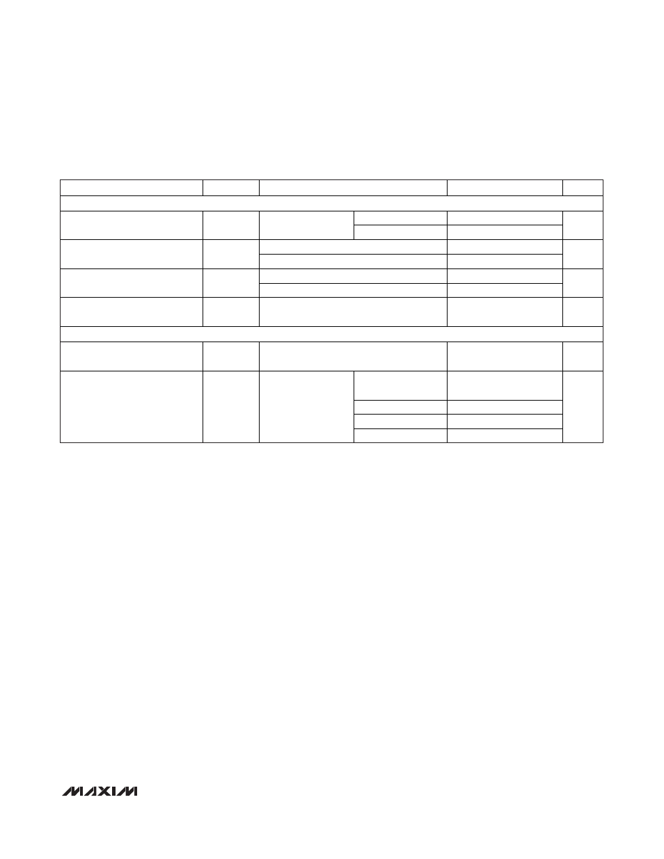
ELECTRICAL CHARACTERISTICS (continued)
(V
IN
= 12V, V
DD
= V
CC
= V
EN1
= V
EN2
= 5V, V
REFIN1
= 2V, SKIP = GND, T
A
= -40°C to +105°C, unless otherwise noted.) (Note 4)
PARAMETER
SYMBOL
CONDITIONS
MIN
MAX
UNITS
GATE DRIVERS
Low state (pulldown)
4.5
DH1, DH2 Gate-Driver
On-Resistance
R
ON(DH)
BST_ - LX_ forced to
5V
High state (pullup)
4.0
High state (pullup)
3
DL1, DL2 Gate-Driver
On-Resistance
R
ON(DL)
Low state (pulldown)
2.5
DH_ low to DL high
8
42
Driver Propagation Delay
DL_ low to DH high
12
48
ns
Internal BST_ Switch
On-Resistance
R
BST_
I
BST_
= 10mA, V
DD
= 5V
12
INPUTS AND OUTPUTS
EN1, EN2 Logic-Input Threshold
EN1, EN2 rising edge;
hysteresis = 300mV/600mV (min/max)
1.20
2.20 V
High (5V)
V
CC
-
0.3
Open (3.3V)
3.0
3.6
Ref (2.0V)
1.7
2.3
Quad-Level Input Logic Levels
SKIP, ILIM1, ILIM2
Low (GND)
0.4
V