Table 4. fault protection and shutdown operation – Rainbow Electronics MAX17008 User Manual
Page 27
Undervoltage Protection (UVP)
When the feedback voltage drops below the undervolt-
age threshold, the controller immediately pulls PGOOD
low and triggers a 200μs one-shot timer. If the feed-
back voltage remains below the undervoltage fault
threshold for the entire 200μs, then the undervoltage
fault latch of the faulted SMPS is set and that SMPS
begins its shutdown sequence. When the internal target
voltage drops below 0.1V, the MAX17007A/MAX17008
force DL low for the faulted SMPS. Toggle EN or cycle
V
CC
power below V
CC
POR to clear the fault latch and
restart the controller.
The undervoltage thresholds are -200mV for SMPS1
(fixed 1.05V and adjustable REFIN1), -200mV for
SMPS2 in preset mode (fixed 1.5V output), and -100mV
for SMPS2 in adjustable mode (0.7V feedback).
A UV fault on one side does not affect the other side.
Thermal-Fault Protection (T
SHDN
)
The MAX17007A/MAX17008 feature a thermal-fault pro-
tection circuit. When the junction temperature rises
above +160°C, a thermal sensor activates the fault
latch, pulls PGOOD low, and shuts down the controller.
Both DL and DH are pulled low. Toggle EN or cycle
V
CC
power below V
CC
POR to reactivate the controller
after the junction temperature cools by 15°C.
V
CC
POR and UVLO
Each SMPS of the MAX17007A/MAX17008 is enabled
when its respective EN is driven high. On the first rising
EN, the reference powers up first. Once the reference
exceeds its undervoltage lockout (UVLO) threshold
(~ 60μs), the internal analog blocks are turned on and
masked by a 140μs one-shot delay in order to allow the
bias circuitry and analog blocks enough time to settle
to their proper states. With the control circuitry reliably
powered up, the PWM controller begins switching. The
second rising EN, if controlled separately, also has the
140μs one-shot delay before its first DH pulse.
Power-on reset (POR) occurs when V
CC
rises above
approximately 3V, resetting the fault latch and preparing
the controller for operation. The V
CC
UVLO circuitry
inhibits switching until V
CC
rises above 4.25V. The con-
troller powers up the reference once the system enables
the controller, V
CC
exceeds 4.25V, and either EN is dri-
ven high. With the reference in regulation, the controller
ramps the output voltage to the target voltage with a
1.3mV/μs slew rate for SMPS1 and 0.65mV/μs for SMPS2.
If the V
CC
voltage drops below 4.25V, the controller
assumes that there is not enough supply voltage to make
valid decisions. To protect the output from overvoltage
faults, the controller shuts down immediately and forces
a high-impedance output (DL and DH pulled low).
MAX17007A/MAX17008
Dual and Combinable QPWM Graphics
Core Controllers for Notebook Computers
______________________________________________________________________________________
27
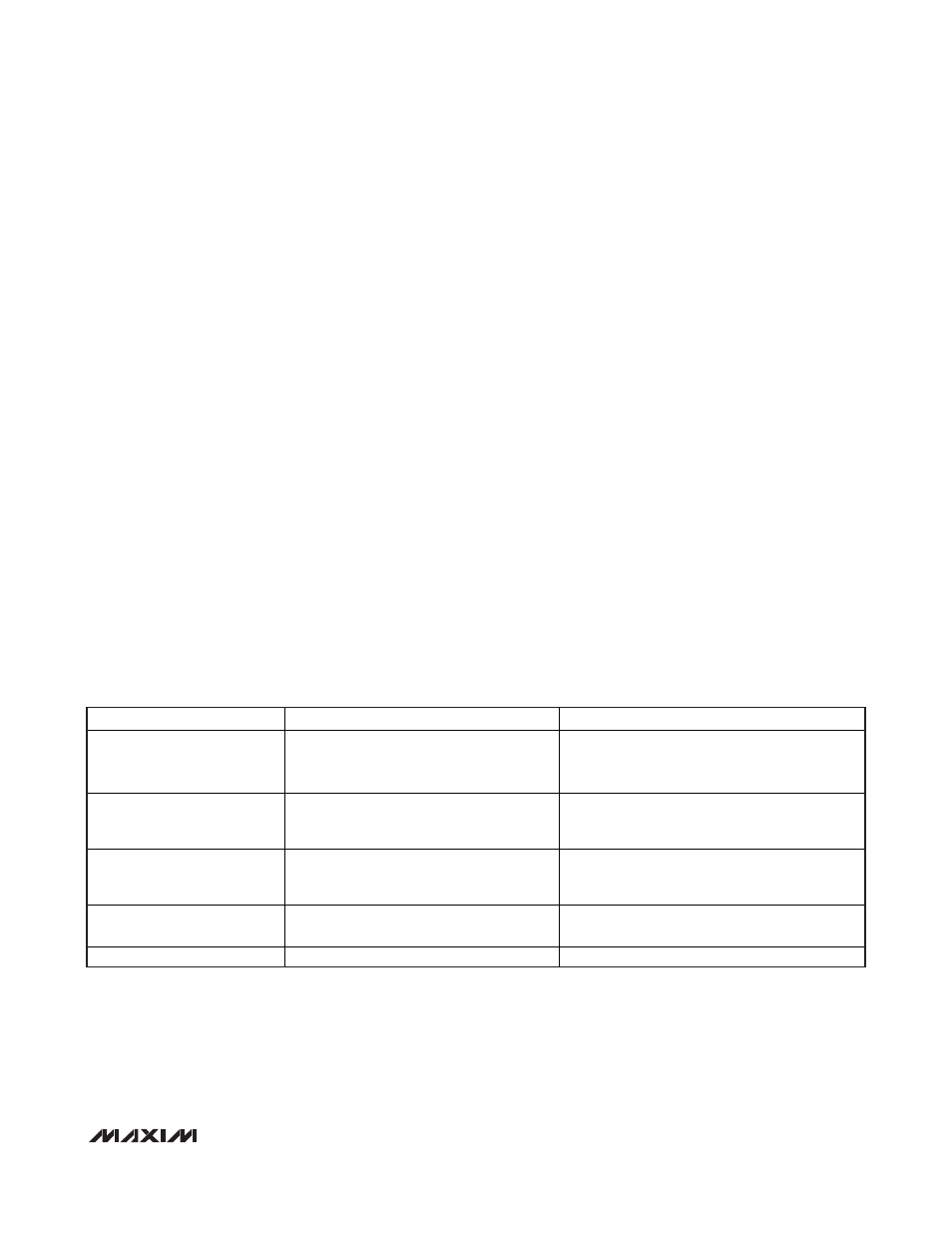
MODE
CONTROLLER STATE
DRIVER STATE
Shutdown (EN_ = High to Low)
Output UVP (Latched)
Thermal Fault (Latched)
Voltage soft-shutdown initiated. Error
amplifier target slowly ramped down to
GND.
DL_ low and DH_ low after soft-shutdown
completed, internal 10 discharge on CSL_
activated. (Target < 0.1V.)
Output OVP (Latched)
Controller shuts down and internal target
slews down. Controller remains off until
EN_ toggled or V
CC
power cycled.
DL_ immediately forced high, DH_ pulled low
(high-side MOSFET disabled).
V
CC
UVLO Falling Edge
Controller shuts down and the internal
target slews down. Controller remains off
until V
CC
rises back above UVLO threshold.
DL_ low, DH_ low, internal 10 discharge on
CSL_ activated.
V
CC
UVLO Rising Edge
SMPS controller enabled (assuming EN_
pulled high).
DL_, DH_ switching.
V
CC
POR
SMPS inactive.
DL_ low.
Table 4. Fault Protection and Shutdown Operation