Rainbow Electronics MAX17008 User Manual
Page 30
MAX17007A/MAX17008
Output Capacitor Selection
The output filter capacitor must have low enough effec-
tive series resistance (ESR) to meet output ripple and
load-transient requirements, yet have high enough ESR
to satisfy stability requirements.
In core and chipset converters and other applications
where the output is subject to large-load transients, the
output capacitor’s size typically depends on how much
ESR is needed to prevent the output from dipping too
low under a load transient. Ignoring the sag due to finite
capacitance:
In low-power applications, the output capacitor’s size
often depends on how much ESR is needed to maintain
an acceptable level of output ripple voltage. The output
ripple voltage of a step-down controller equals the total
inductor ripple current multiplied by the output capacitor’s
ESR. The maximum ESR to meet ripple requirements is:
where f
SW
is the switching frequency.
With most chemistries (polymer, tantalum, aluminum
electrolytic), the actual capacitance value required
relates to the physical size needed to achieve low ESR
and the chemistry limits of the selected capacitor tech-
nology. Ceramic capacitors provide low ESR, but the
capacitance and voltage rating (after derating) are
determined by the capacity needed to prevent V
SAG
and V
SOAR
from causing problems during load tran-
sients. Generally, once enough capacitance is added
to meet the overshoot requirement, undershoot at the
rising load edge is no longer a problem (see the V
SAG
and V
SOAR
equations in the
Transient Response
sec-
tion). Thus, the output capacitor selection requires
carefully balancing capacitor chemistry limitations
(capacitance vs. ESR vs. voltage rating) and cost.
Output Capacitor Stability Considerations
For Quick-PWM controllers, stability is determined by the
in-phase feedback ripple relative to the switching frequen-
cy, which is typically dominated by the output ESR. The
boundary of instability is given by the following equation:
where C
OUT
is the total output capacitance, R
ESR
is the
total ESR of the output capacitors, R
CS
is the current-
sense resistance, and A
CS
is the current-sense gain as
determined by the ILIM setting. A
CS
equals 2, 2.67, 4, and
8 for ILIM settings of 5V, 3.3V, 2V, and GND, respectively.
For a 300kHz application, the effective zero frequency
must be well below 95kHz, preferably below 50kHz. For
the standard application circuit with ceramic output
capacitors, the output ripple cannot be relied upon to
be in phase with the inductor current due to the low
ESR of the ceramic capacitors. Stability is mainly
dependent on the current-sense gain. With ILIM = 2V,
A
CS
= 4, and an effective current-sense resistance of
approximately 3.5m
Ω, then the ESR zero works out to:
1/[2
π x (2 x 330μF + 5 x 10μF) x 4 x 3.5mΩ] = 16kHz
This is well within the stability requirements.
R
R
A
R
EFF
ESR
CS CS
=
+
R
f
C
EFF
SW OUT
≥
1
2
f
R
C
SW
EFF OUT
π
π
≥
1
2
R
V f
L
V
V
V
V
ESR
IN SW
IN
OUT
OUT
RIPPLE
≤
(
)
⎡
⎣
⎢
⎢
⎤
⎦
⎥
⎥
-
R
R
V
I
ESR
PCB
STEP
LOAD MAX
+
(
)
≤
Δ
(
)
Dual and Combinable QPWM Graphics
Core Controllers for Notebook Computers
30
______________________________________________________________________________________
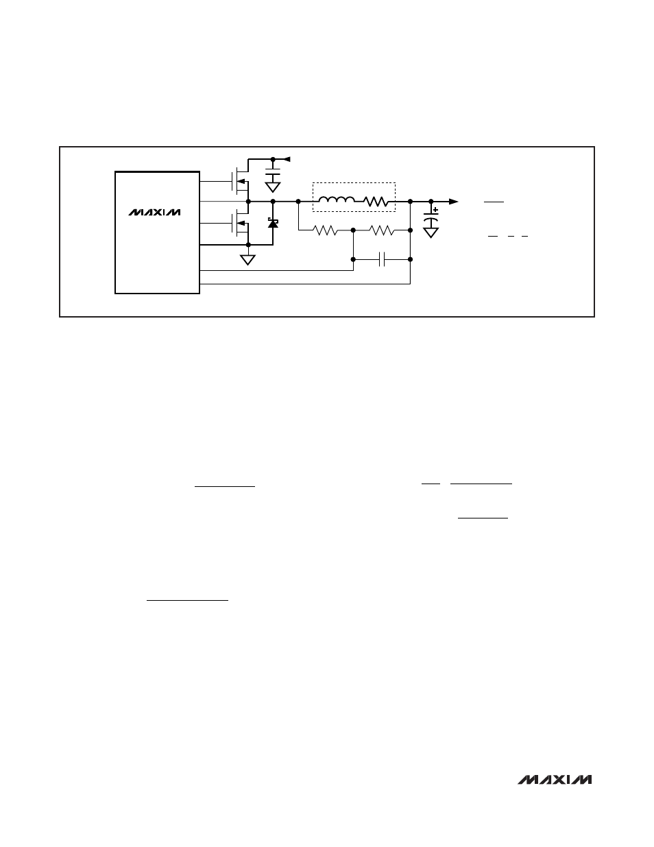
MAX17007A
MAX17008
C
OUT
INPUT (V
IN
)
C
IN
b) LOSSLESS INDUCTOR SENSING
FOR THERMAL COMPENSATION:
R2 SHOULD CONSIST OF AN NTC RESISTOR IN
SERIES WITH A STANDARD THIN-FILM RESISTOR.
CSL_
CSH_
PGND
DL_
DH_
LX_
C
EQ
R1
R2
N
H
N
L
D
L
L
INDUCTOR
R
DCR
R
CS
=
R2
R
DCR
R1 + R2
R
DCR
=
L
[
1 + 1
]
C
EQ
R1 R2
Figure 14. Current-Sense Configurations (Sheet 2 of 2)