Rainbow Electronics MAX17008 User Manual
Page 23
Valley Current-Limit Protection
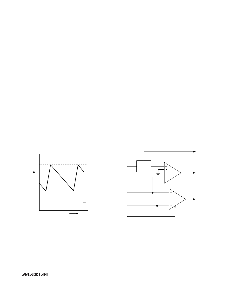
The current-limit circuit employs a unique “valley” cur-
rent-sensing algorithm that senses the inductor current
across the output current-sense element—inductor
DCR or current-sense resistor, which generates a volt-
age between CSH_ and CSL_. If the current exceeds
the valley current-limit threshold during the low-side
MOSFET conduction time, the PWM controller is not
allowed to initiate a new cycle. The valley current-limit
threshold is set by the four-level ILIM_ pin, with selec-
table limits of 15mV, 30mV, 45mV, and 60mV.
The actual peak current is greater than the valley cur-
rent-limit threshold by an amount equal to the inductor
ripple current (Figure 7). Therefore, the exact current-
limit characteristic and maximum load capability are a
function of the inductor value and battery voltage.
When combined with the undervoltage protection cir-
cuit, this current-limit method is effective in almost
every circumstance. See Figure 8.
In forced-PWM mode, the MAX17007A/MAX17008 also
implement a negative current limit to prevent excessive
reverse inductor currents when V
OUT
is sinking current.
The negative current-limit threshold is set to approxi-
mately 120% of the positive current limit.
In combined mode, ILIM1 sets the per-phase current
limit for both phases.
MOSFET Gate Drivers (DH, DL)
The DH and DL drivers are optimized for driving moder-
ate-sized high-side, and larger low-side power
MOSFETs. This is consistent with the low duty factor
seen in notebook applications, where a large V
IN
-
V
OUT
differential exists. The high-side gate driver (DH)
sources and sinks 1.2A, and the low-side gate driver
(DL) sources 1.0A and sinks 2.4A. This ensures robust
gate drive for high-current applications. The DH floating
high-side MOSFET driver is powered by internal boost
switch charge pumps at BST, while the DL synchro-
nous-rectifier driver is powered directly by the 5V bias
supply (V
DD
).
MAX17007A/MAX17008
Dual and Combinable QPWM Graphics
Core Controllers for Notebook Computers
______________________________________________________________________________________
23
INDUCTOR CURRENT
I
LIMIT
I
LOAD
0
TIME
I
PEAK
I
LIM(VAL)
= I
LOAD(MAX)
1-
LIR
2
(
)
Figure 7. “Valley” Current-Limit Threshold Point
CSH
ILIM
CSL
SKIP
ZERO
CROSSING
VALLEY
CURRENT
LIMIT
QUAD-LEVEL
DECODE
CURRENT-
SENSE
GAIN
Figure 8. Current-Limit Block Diagram