Pin description (continued) – Rainbow Electronics MAX17008 User Manual
Page 13
MAX17007A/MAX17008
Dual and Combinable QPWM Graphics
Core Controllers for Notebook Computers
______________________________________________________________________________________
13
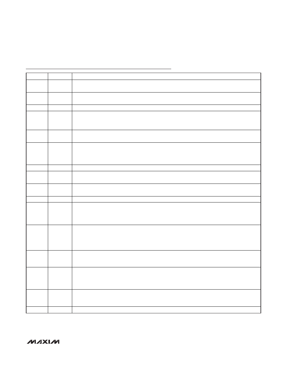
Pin Description (continued)
PIN
NAME
FUNCTION
14 LX1
Inductor Connection for SMPS1. Connect LX1 to the switched side of the inductor. LX1 serves as the
lower supply rail for the DH1 high-side gate driver.
15 BST1
Bootstrap Capacitor Connection for SMPS1. The MAX17007A/MAX17008 include an internal boost
switch/diode connected between V
DD
and BST1. Connect to an external capacitor as shown in Figure 1.
16
GND
Ground. Analog and power ground connection for the low-side gate driver of SMPS1.
17 DL1
Low-Side Gate Driver Output for SMPS1. DL1 swings from GND to V
DD
. DL1 is forced low after the shutdown
sequence has completed. DL1 is also forced high when an output overvoltage fault is detected, overriding
any negative current-limit condition that may be present. DL1 is forced low in V
CC
UVLO.
18 V
DD
5V Driver Supply Input. Connect V
DD
to V
CC
through a 10
resistor. Bypass to ground through a 2.2μF or
greater ceramic capacitor. V
DD
is internally connected to the BST diodes and the low-side gate drivers.
19 DL2
Low-Side Gate-Driver Output for SMPS2. DL2 swings from PGND to V
DD
. DL2 is forced low after the
shutdown sequence has completed. DL2 is also forced high when an output overvoltage fault is
detected, overriding any negative current-limit condition that may be present. DL2 is forced low in V
CC
UVLO.
20
PGND
Power Ground for the Low-Side Gate Driver of SMPS2
21 BST2
Bootstrap Capacitor Connection for SMPS2. The MAX17007A/MAX17008 include an internal boost switch/
diode connected between V
DD
and BST2. Connect to an external capacitor as shown in Figure 1.
22 LX2
Inductor Connection for SMPS2. Connect LX2 to the switched side of the inductor. LX2 serves as the
lower supply rail for the DH2 high-side gate driver.
23
DH2
High-Side Gate-Driver Output for SMPS2. DH2 swings from LX2 to BST2. DH2 is low in shutdown.
24 PGOOD2
Open-Drain Power-Good Output for SMPS2. PGOOD2 is low when the FB2 voltage is more than 100mV
below or 150mV above the target voltage, during soft-start, and in shutdown. After the SMPS2 soft-start
circuit has terminated, PGOOD2 becomes high impedance 200μs after the output is in regulation.
In combined mode, PGOOD2 is not used and can be left open.
25 EN2
SMPS2 Enable Input. Connect to V
CC
for normal operation. Pull EN2 low to disable SMPS2. The
controller slowly ramps down the output voltage to ground, and after the target voltage reaches 0.1V,
the controller forces DL2 low. When both EN1 and EN2 are low, the device enters the low-power
shutdown state.
In combined mode, EN2 is not used and should be connected to GND.
26 CSH2
Positive Current-Sense Input for SMPS2. Connect to the positive terminal of the current-sense element.
Figure 14 describes two different current-sensing options—using accurate sense resistors or lossless
inductor DCR sensing.
27 CSL2
Output-Sense and Negative Current-Sense Input for SMPS2. When using the internal preset 1.5V
feedback divider (FB2 = REF), the controller uses CSL2 to sense the output voltage. Connect to the
negative terminal of the current-sense element. Figure 14 describes two different current-sensing
options—using accurate sense resistors or lossless inductor DCR sensing.
28 FB2
SMPS2 Feedback Input. Adjust the SMPS2 voltage with a resistive voltage-divider between SMPS2
output and GND. Connect FB2 to REF for preset 1.5V output. Tie FB2 to V
CC
to configure the
MAX17007A/MAX17008 for combined-mode operation.
—
EP
Exposed Backside Pad. Connect to analog ground.