Rainbow Electronics MAX17008 User Manual
Page 22
MAX17007A/MAX17008
When SKIP is pulled to GND, the MAX17007A/MAX17008
remain in pulse-skipping mode. Since the output is not
able to sink current, the timing for negative dynamic out-
put-voltage transitions depends on the load current and
output capacitance. Letting the output voltage drift down
is typically recommended in order to reduce the potential
for audible noise since this eliminates the input current
surge during negative output-voltage transitions. Figure 5
shows the pulse-skipping/discontinuous crossover point.
Ultrasonic Mode (
S
SK
KIIP
P
= Open = 3.3V)
Leaving SKIP unconnected or connecting SKIP to 3.3V
activates a unique pulse-skipping mode with a mini-
mum switching frequency of 25kHz. This ultrasonic
pulse-skipping mode eliminates audio-frequency mod-
ulation that would otherwise be present when a lightly
loaded controller automatically skips pulses. In ultra-
sonic mode, the controller automatically transitions to
fixed-frequency PWM operation when the load reaches
the same critical conduction point (I
LOAD(SKIP)
) that
occurs when normally pulse skipping.
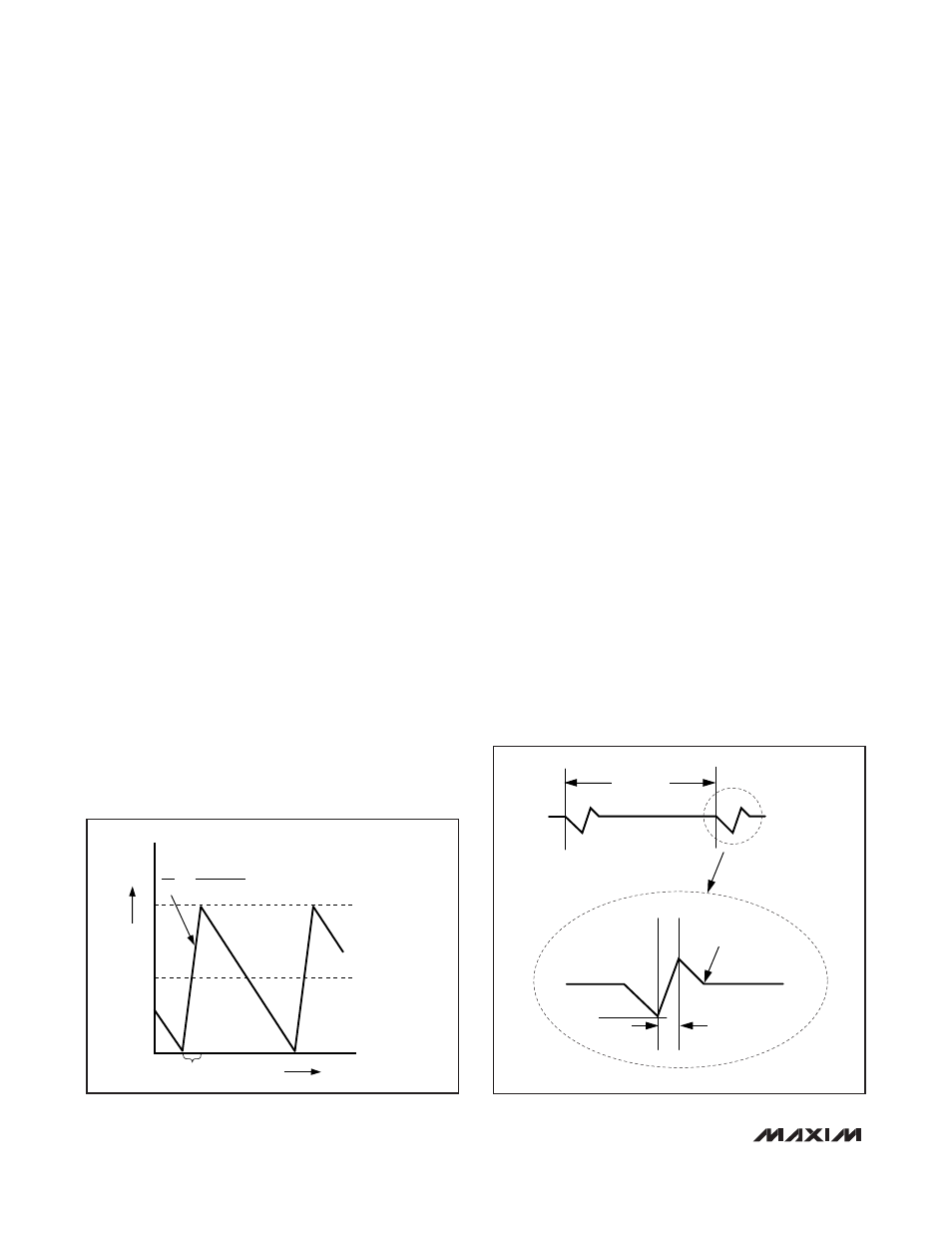
An ultrasonic pulse occurs when the controller detects
that no switching has occurred within the last 30μs.
Once triggered, the ultrasonic controller pulls DL high,
turning on the low-side MOSFET to induce a negative
inductor current (Figure 6). After the inductor current
reaches the negative ultrasonic current threshold, the
controller turns off the low-side MOSFET (DL pulled
low) and triggers a constant on-time (DH driven high).
When the on-time has expired, the controller reenables
the low-side MOSFET until the controller detects that
the inductor current dropped below the zero-crossing
threshold. Starting with a DL pulse greatly reduces the
peak output voltage when compared to starting with a
DH pulse.
The output voltage at the beginning of the ultrasonic
pulse determines the negative ultrasonic current thresh-
old, resulting in the following equations for SMPS1:
(SMPS1 adjustable mode)
(SMPS1 preset mode)
where V
CSL1
> V
REFIN1
in adjustable mode, V
CSL1
>
1.05V in preset mode, and R
CS1
is the current-sense
resistance seen across CSH1 to CSL1.
Similarly for SMPS2:
(SMPS2 adjustable mode)
(SMPS2 preset mode)
where V
CSL2
> 0.7V in adjustable mode, V
CSL2
> 1.5V
in preset mode, and R
CS2
is the current-sense resis-
tance seen across CSH2 to CSL2.
In combined mode, ultrasonic mode setting is disabled,
and the SKIP = open (3.3V) setting is identical to the
SKIP = GND setting.
V
I
R
V V
ISONIC
L
CS
CSL
2
2
2
2
1 5
0 65
.
.
=
=
(
)
×
-
V
I
R
V V
ISONIC
L
CS
FB
2
2
2
2
0 7
0 65
.
.
=
=
(
)
×
-
V
I R
V V
ISONIC
L
CS
CSL
1
1
1
1
1 05
0 65
.
.
=
=
(
)
×
-
V
I R
V
V
ISONIC
L
CS
REFIN
CSL
1
1
1
1
1
0 65
.
=
=
(
)
×
-
Dual and Combinable QPWM Graphics
Core Controllers for Notebook Computers
22
______________________________________________________________________________________
INDUCTOR CURRENT
I
LOAD
= I
PEAK
/2
ON-TIME
0
TIME
I
PEAK
L
V
IN
- V
OUT
ΔI
Δt
=
Figure 5. Pulse-Skipping/Discontinuous Crossover Point
ON-TIME (t
ON
)
I
SONIC
0
ZERO-CROSSING
DETECTION
INDUCTOR
CURRENT
40
μs (MAX)
Figure 6. Ultrasonic Waveform