Detailed description – Rainbow Electronics MAX16014 User Manual
Page 6
MAX16010–MAX16014
Detailed Description
The MAX16010–MAX16014 is a family of ultra-small, low-
power, overvoltage protection circuits for high-voltage,
high-transient systems such as those found in automo-
tive, telecom, and industrial applications. These devices
operate over a wide 5.5V to 72V supply voltage range,
making them also suitable for other applications such as
battery stacks, notebook computers, and servers.
The MAX16010 and MAX16011 offer two independent
comparators for monitoring both undervoltage and
overvoltage conditions. These comparators offer open-
drain outputs capable of handling voltages up to 72V.
The MAX16010 features complementary enable inputs
(EN/EN), while the MAX16011 features an active-high
enable input and a selectable active-high/low OUTB
output.
The MAX16012 offers a single comparator and an inde-
pendent reference output. The reference output can be
directly connected to either the inverting or noninvert-
ing input to select the comparator output logic.
The MAX16013 and MAX16014 are overvoltage protec-
tion circuits that are capable of driving two p-channel
MOSFETs to prevent reverse battery and overvoltage
conditions. One MOSFET (P1) eliminates the need for
external diodes, thus minimizing the input voltage drop.
While the second MOSFET (P2) isolates the load or reg-
ulates the output voltage during an overvoltage condi-
tion. The MAX16014 keeps the MOSFET (P2) latched
off until the input power is cycled.
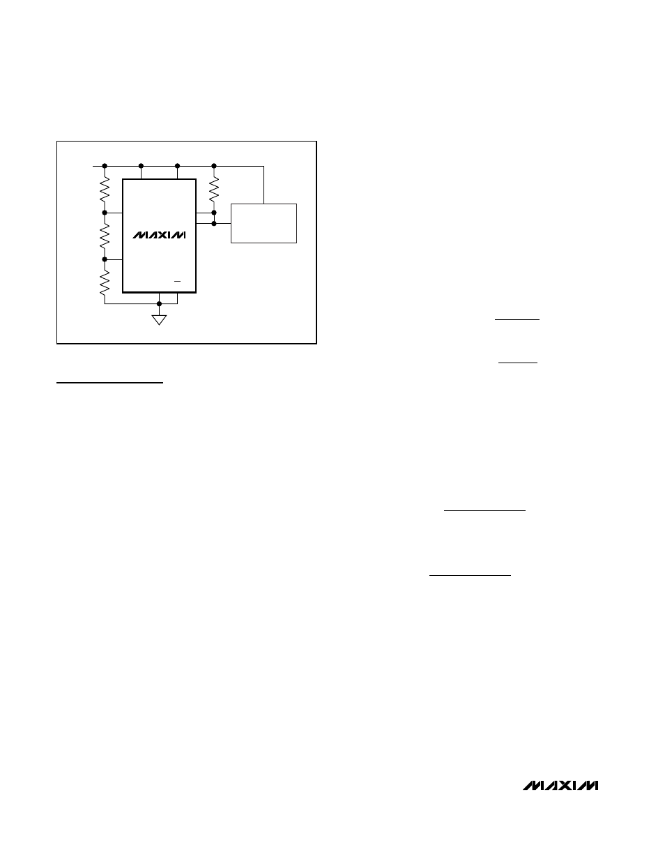
Voltage Monitoring
The MAX16010/MAX16011 include undervoltage and
overvoltage comparators for window detection (see
Figure 1). OUT_ asserts high when the monitored volt-
age is within the selected “window.” OUTB asserts low
when the monitored voltage falls below the lower
(V
TRIPLOW
) limit of the window, or OUTA asserts low if
the monitored voltage exceeds the upper limit
(V
TRIPHIGH
). The application in Figure 1 shows OUT_
enabling the DC-DC converter when the monitored volt-
age is in the selected window.
The resistor values R1, R2, and R3 can be calculated
as follows:
where R
TOTAL
= R1 + R2 + R3.
Use the following steps to determine the values for R1,
R2, and R3.
1) Choose a value for R
TOTAL
, the sum of R1, R2, and
R3. Because the MAX16010/MAX16011 have very
high input impedance, R
TOTAL
can be up to 5M
Ω.
2) Calculate R3 based on R
TOTAL
and the desired
upper trip point:
3) Calculate R2 based on R
TOTAL
, R3, and the desired
lower trip point:
4) Calculate R1 based on R
TOTAL
, R3, and R2:
R1 = R
TOTAL
- R2 - R3
The MAX16012 has both inputs of the comparator avail-
able with an integrated 1.30V reference (REF). When the
voltage at IN+ is greater than the voltage at IN- then OUT
goes high. When the voltage at IN- is greater than the
voltage at IN+ then OUT goes low. Connect REF to IN+
or IN- to set the reference voltage value. Use an external
resistive divider to set the monitored voltage threshold.
R
V
R
V
R
TH
TOTAL
TRIPLOW
2
3
=
×
−
−
R
V
R
V
TH
TOTAL
TRIPHIGH
3
=
×
+
V
V
R
R
TRIPHIGH
TH
TOTAL
=
+
3
V
V
R
R
R
TRIPLOW
TH
TOTAL
=
+
−
2
3
Ultra-Small, Overvoltage Protection/
Detection Circuits
6
_______________________________________________________________________________________
MAX16010
DC-DC
REGULATOR
IN
EN
INA+
INB-
OUTB
OUTA
R3
R2
R1
+48V
EN
GND
V
CC
EN
Figure 1. MAX16010 Monitor Circuit