Pin description – Rainbow Electronics MAX16014 User Manual
Page 5
MAX16010–MAX16014
Ultra-Small, Overvoltage Protection/
Detection Circuits
_______________________________________________________________________________________
5
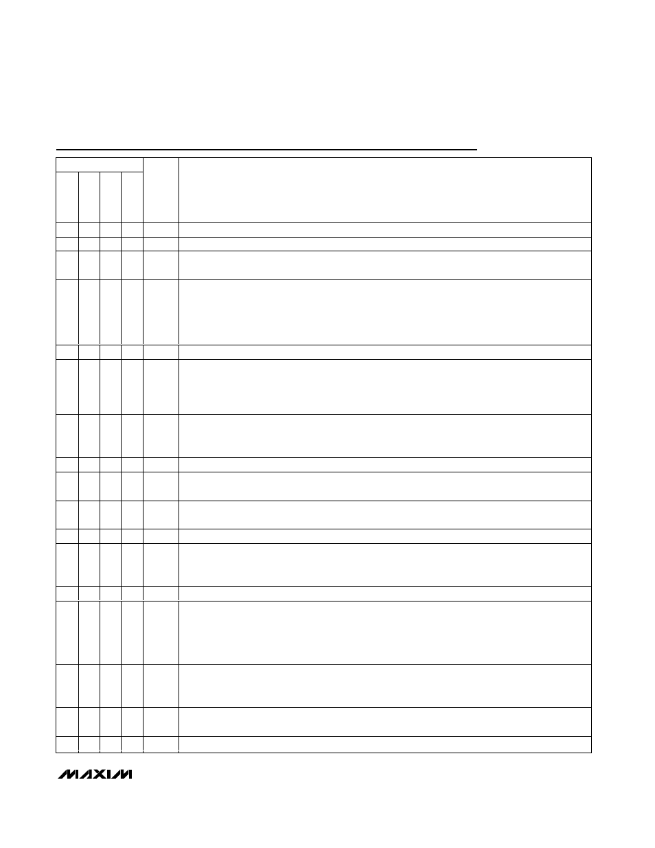
Pin Description
PIN
MAX16010
MAX16011
MAX16012
MAX16013
MAX16014
NAME
FUNCTION
1
1
1
1
V
CC
Positive-Supply Input Voltage. Connect V
CC
to a 5.5V to 72V supply.
2
2
2
2
GND
Ground
3
—
—
—
EN
Active-Low Enable Input. Drive EN low to turn on the voltage detectors. Drive EN high to force the
OUTA and OUTB outputs low. EN is internally pulled up to V
CC
. Connect EN to GND if not used.
4
4
—
—
OUTB
Open-Drain Monitor B Output. Connect a pullup resistor from OUTB to V
CC
. OUTB goes low when
INB- exceeds V
TH+
and goes high when INB- drops below V
TH-
(with LOGIC connected to GND for
the MAX16011). Drive LOGIC high to reverse OUTB’s logic state. OUTB is usually used as an
overvoltage output. OUTB goes low (LOGIC = low) or high (LOGIC = high) when V
CC
drops below
the UVLO threshold voltage.
5
5
—
—
INB-
Adjustable Voltage Monitor Threshold Input
6
6
—
5
EN
Active-High ENABLE Input. For the MAX16010/MAX16011, drive EN high to turn on the voltage
detectors. Drive EN low to force OUTA low and OUTB low (LOGIC = low) or high (LOGIC = high). For
the MAX16013/MAX16014, drive EN high to enhance the p-channel MOSFET (P2), and drive EN low
to turn off the MOSFET. EN is internally pulled down to GND. Connect EN to V
CC
if not used.
7
7
—
—
OUTA
Open-Drain Monitor A Output. Connect a pullup resistor from OUTA to V
CC
. OUTA goes low when
INA+ drops below V
TH-
and goes high when INA+ exceeds V
TH+
. OUTA is usually used as an
undervoltage output. OUTA also goes low when V
CC
drops below the UVLO threshold voltage.
8
8
—
—
INA+
Adjustable Voltage Monitor Threshold Input
—
3
—
—
LOGIC
OUTB Logic-Select Input. Connect LOGIC to GND or V
CC
to configure the OUTB logic. See the
MAX16011 output logic table.
—
—
3
—
OUT
Open-Drain Comparator Output. Connect a pullup resistor from OUT to V
CC
. OUT goes low when
IN+ drops below IN-. OUT goes high when IN+ exceeds IN-.
—
—
4
—
IN-
Inverting Comparator Input
—
—
5
—
REF
Internal 1.30V Reference Output. Connect REF to IN+ for active-low output. Connect REF to IN- for
active-high output. REF can source and sink up to 1µA. Leave REF floating if not used. REF output is
stable with capacitive loads from 0 to 50pF.
—
—
6
—
IN+
Noninverting Comparator Input
—
—
—
3
GATE2
Gate-Driver Output. Connect GATE2 to the gate of an external p-channel MOSFET pass switch.
GATE2 is driven low to the higher of V
CC
- 10V or GND during normal operations and quickly shorted
to V
CC
during an overvoltage condition (SET above the internal threshold). GATE2 is shorted to V
CC
when the supply voltage goes below the UVLO threshold voltage. GATE2 is shorted to V
CC
when EN
is low.
—
—
—
4
SET
Device Overvoltage Threshold Adjustment Input. Connect SET to an external resistive divider network
to adjust the desired overvoltage disable or overvoltage limit threshold (see the Typical Application
Circuit and Overvoltage Limiter section).
—
—
—
6
GATE1
Gate-Driver Output. Connect GATE1 to the gate of an external p-channel MOSFET to provide low
drop reverse voltage protection.
—
—
—
—
EP
Exposed Pad. Connect EP to GND.