Rough Country 253X User Manual
Page 10
49. Remove the ABS wire and clamp from the stock knuckle.
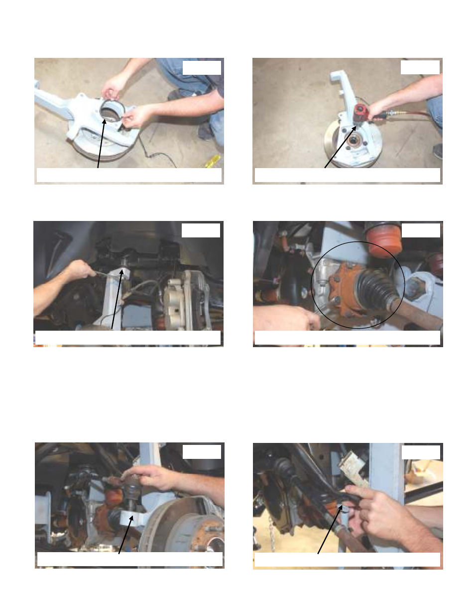
50. Install the o-ring as shown in Photo 37.
51. Install bearing assembly in lifted knuckle with the factory hardware. Tighten using a 21mm socket. See Photo 38.
52. Install knuckle on the lower and upper control arms. See Photo 39.
53. Reinstall axle shaft in the knuckle bearing and on the differential with the stock hardware. Tighten axle shaft bolts as
shown in Photo 40 with a 15mm socket / wrench and the axle nut using a 33mm socket.
54. Inspect the supplied brake lines and determine driver and passenger side.
55. Remove the rubber brake line from the hard line on the frame using a 3/8” wrench. Replace with the appropriate
brake line and tighten.
56. Remove the stock line on the caliper and install the brake line on the brake caliper using the factory hardware and
new 3/8” Brake Crush washers from 1253Bag5.
57. Install the caliper on the knuckle using factory hardware. Tighten using a 21mm socket / wrench. Using the supplied
zip ties from 1253Bag5, secure to the brake lines to the tab on the knuckle.
58. Install tie-rod on the knuckle with the factory hardware. Tighten using a 21mm socket / wrench. See Photo 41.
59. Photo 42 shows the location of the supplied sway bar washers. The washers from 1253Bag7 will install on the upper
and lower bushings of both the sway bar and the lower control arm.
Photo 37
Photo 38
Photo 39
Photo 40
Photo 41
Photo 42
REINSTALL THE O-RING IN NEW KNUCKLE
REINSTALL THE BEARING IN NEW KNUCKLE
INSTALL KNUCKLE ON THE CONTROL ARMS
REINSTALL THE SHAFTS TO THE DIFF
INSTALL THE TIE ROD ENDS IN KNUCKLES
INSTALL SWAY LINK BODY AND WASHERS