Rough Country 242N2 User Manual
Page 8
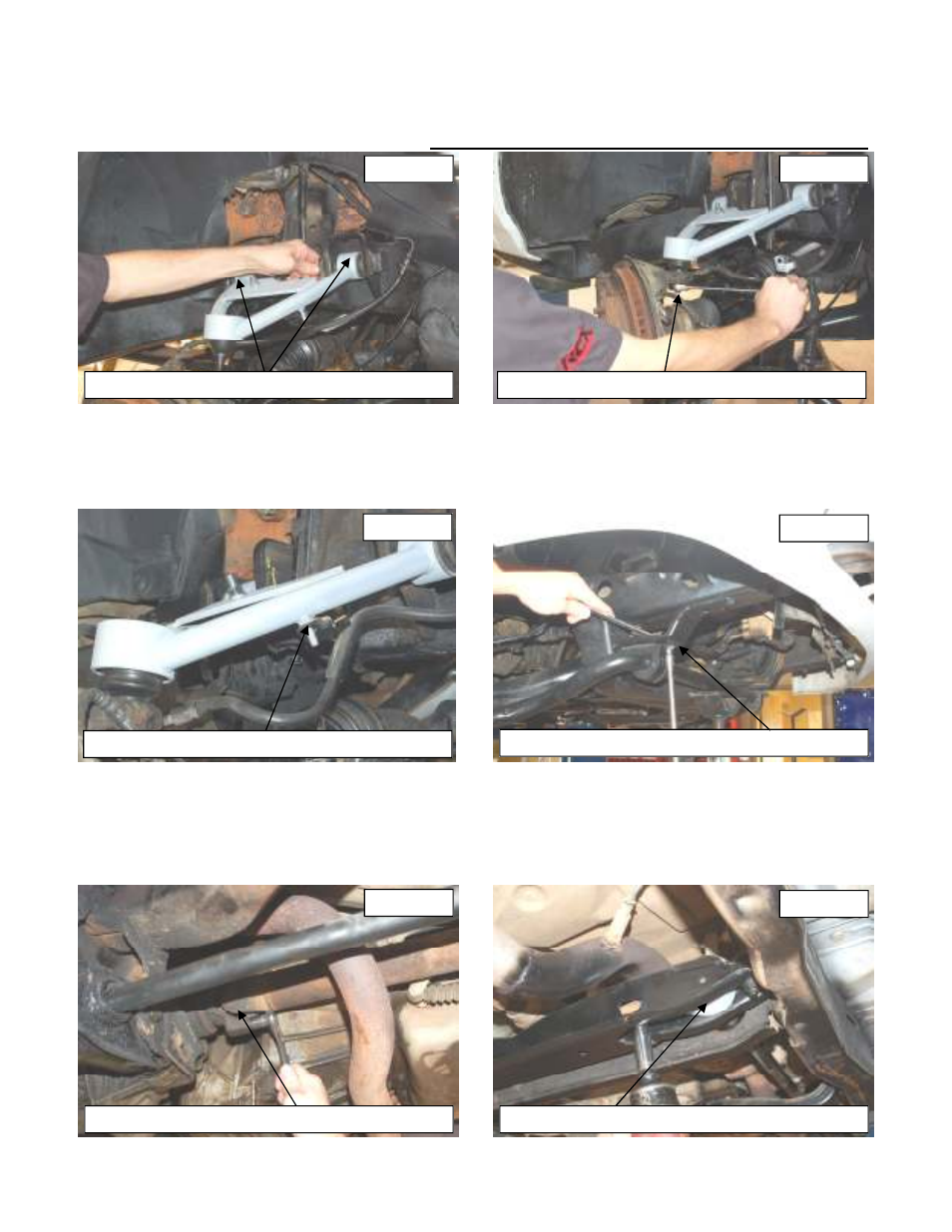
51. Locate appropriate arm for driver and passenger side and install the upper control arms in the stock location using
the stock hardware. See Photo 36. Do not tighten the arms at this time. Passenger side shown. They will be tight-
ened when the vehicle is on the ground.
52. Install the ball joint in the knuckle and install the supplied castle nut and thick washer. Tighten using a 19mm wrench
and install the supplied cotter pin. See Photo 37. NOTE: The Thick washer must be installed on the ball joint.
53. Tighten the control arm bolts on the frame using a 18mm socket / wrench.
54. Install the tie rod end on the knuckle with the factory castle nut and tighten using a 18MM wrench and install the cot-
ter pin.
55. Install the brake line on the new control arm as shown in Photo 38 and secure with the 1/4” lock nuts and flat wash-
ers.
56. Reinstall the stock hardware on the sway bar and tighten using a 10mm socket and 15mm wrench. See Photo 39.
57. Reinstall drive shaft on the differential with the stock hardware. Tighten using a 11mm wrench. See Photo 40.
58. Insert the new torsion bar key in the cross-member and slide the torsion bar inside the key. Make sure the torsion
bar is fully engaged in the torsion bar adjuster.
59. Install the factory threaded block and bolt. See Photo 41. Tighten bolt to where the bolt is halfway threaded in the
threaded block using a 18mm socket. DO NOT max the torsion bar keys with the adjuster bolt. This will result
in a harsh ride. Front vehicle height will be adjusted to level the front with the rear.
INSTALL THE ARM ON THE KNUCKLE
INSTALL THE BRAKE LINE ON THE ARM
REINSTALL THE SWAY BAR
PHOTO 36
PHOTO 37
PHOTO 38
PHOTO 39
PHOTO 40
PHOTO 41
INSTALL THE ARM IN THE STOCK MOUNT
REINSTALL THE DRIVESHAFT HARDWARE
INSTALL THE TORSION BAR KEYS