Construction instructions for standpipe, Mounting and installation – VEGA VEGAPULS 56V User Manual
Page 38
38
VEGAPULS 56V
0 %
~45
••
ø 51,2
0,0…0,4
1,5…2
2,9
0,0...0,4
150…500
5…15
2,9…6
100 %
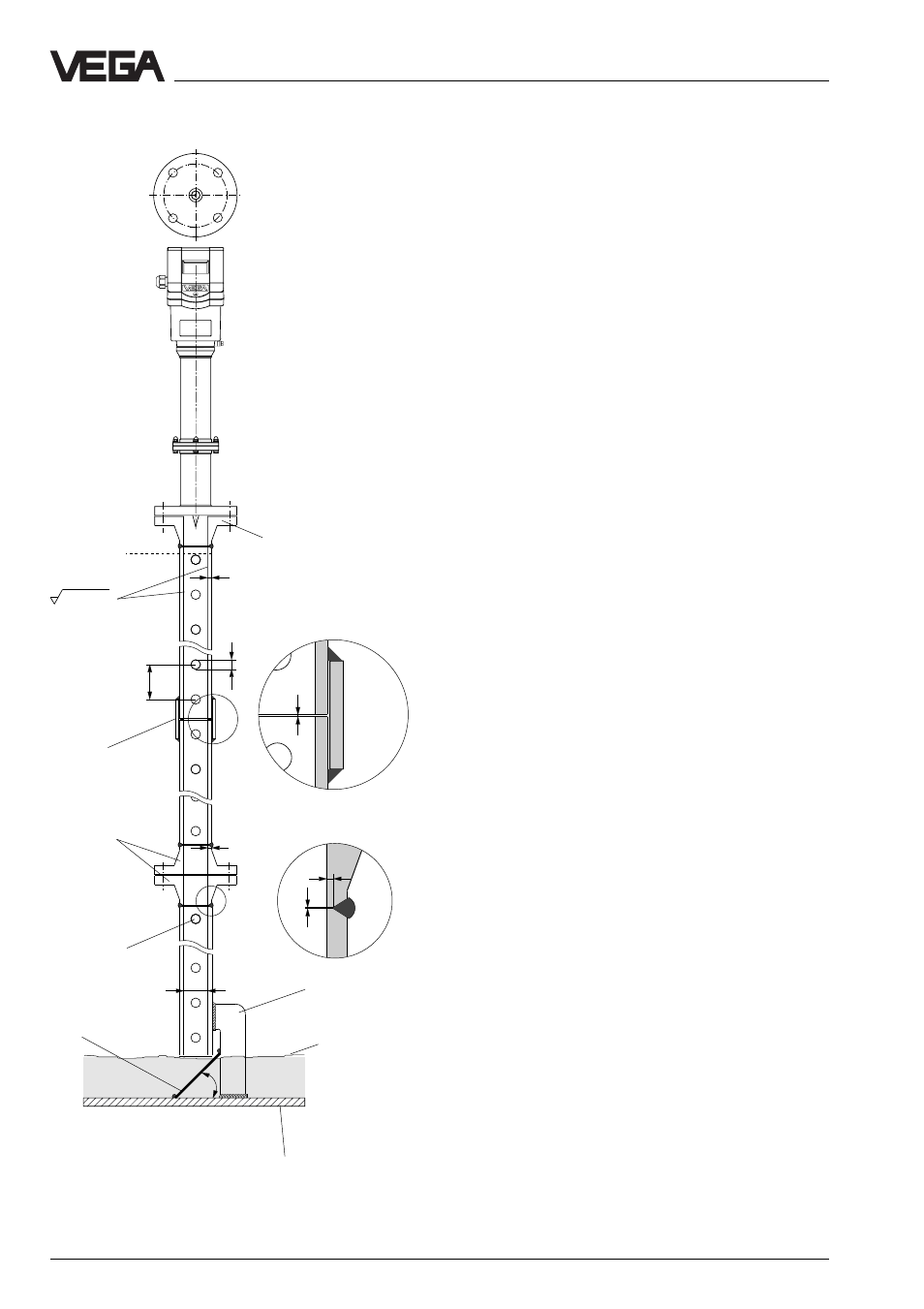
Mounting and installation
Construction instructions for standpipe
Radar sensors for measurement on surge or
bypass pipes are used in flange sizes
DN!50, DN!80, DN!100 and DN!150.
On the left is the construction of a measuring
pipe (surge or bypass pipe) in the example
of a sensor with a DN!50 flange.
The radar sensor with a DN!50 flange is only
in conjunction with a measuring pipe a func-
tional system.
The measuring pipe must be smooth inside
(average roughness Rz!
≤!30). Use as mea-
suring pipe a stainless steel pipe without
joint. Extend the measuring pipe to the re-
quired length with welding neck flanges or
with connecting sleeves. Note that no shoul-
ders are caused in the pipe during welding.
Fasten the pipe and the flange before weld-
ing in alinement with the inner sides.
Do not just weld through the pipe wall.
Roughnesses or joints must be removed
carefully as otherwise strong false echoes
and build-up will be caused.
Flange DN 50
Welding neck flange
Connecting
sleeve
Welding neck
flanges
Welding of the connect-
ing sleeve
Welding of the welding
neck flange
Fastening of
measuring pipe
Vessel bottom
Deflector
Min. product level
to be measured
(0!%)
Rz
≤ 30
Burr the
holes