4 mounting and installation, 1 general installation instructions, Measuring range – VEGA VEGAPULS 56V User Manual
Page 30: False reflections
30
VEGAPULS 56V
,,
,,
,,
,,
,,
,,
,,
,,
,,
,,
,,
,,
,,
,,
,,
,,
,,
,,
,,
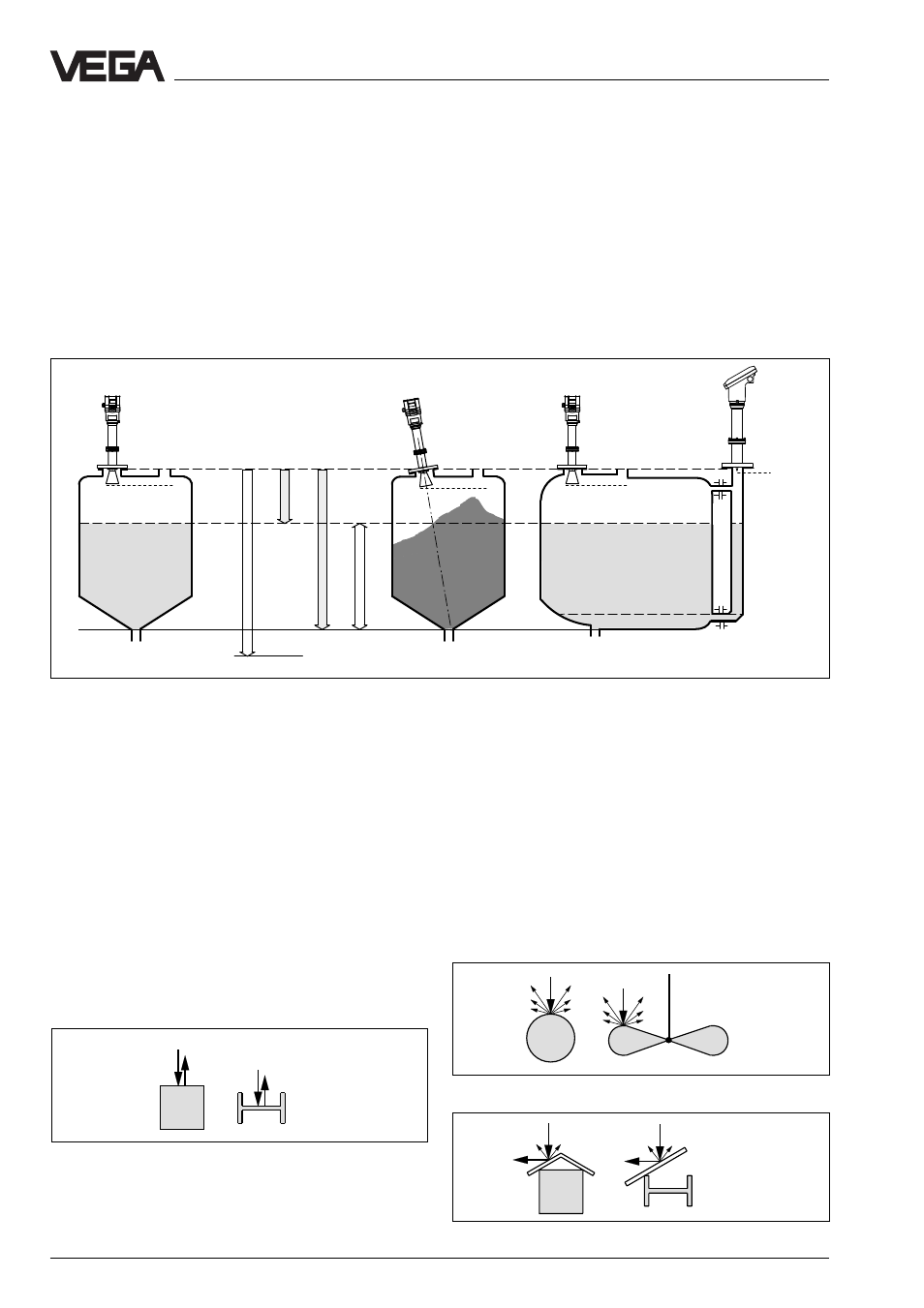
Measuring range (operating range) and max. measuring distance
Note: The use of the sensors in solid applications is restricted.
full
Meas. range
max. meas. distance 20␣ m
4 Mounting and installation
4.1 General installation instructions
Measuring range
The reference plane for the measuring range
of the sensors is the flange face. The measur-
ing range is 0␣ …␣ 20␣ m. For measurements in
surge or bypass pipes (pipe antenna) the
max. measuring distance is reduced (see
"Technical data - Meas. range“).
Please note that for measurements where the
measured product reaches the sensor
flange, build-up on the antenna is possible
which can cause measurement errors. There-
fore the min. distance of the antenna to the
medium should be 5 cm.
Reference plane
empty
Profile with smooth interfering surfaces cause large
false echoes
Round profiles diffuse the radar signals
A deflector causes signal scattering
Mounting and installation
False reflections
Flat obstructions and struts cause large false
reflections. They reflect the signal with high
amplitude.
Round profile interfering surfaces have a
diffuse reflection of the radar signals and
cause false reflections with low density.
Hence they are less critical than reflections
from flat surfaces.
If flat obstructions in the range of the radar
signals cannot be avoided, it is recom-
mended to reflect the interfering signals with
a deflector. Due to this scattering the interfer-
ing signals will be low in amplitude and dif-
fuse so that they can be filtered out by the
sensor.
min. meas.
distance
min.
min. meas.
distance
min. meas.
distance
full
empty