4 adjustment, 1 indicating and adjustment elements, Front plate vegamet 515v – VEGA VEGAMET 515V User Manual
Page 12
12
VEGAMET 515V
4 Adjustment
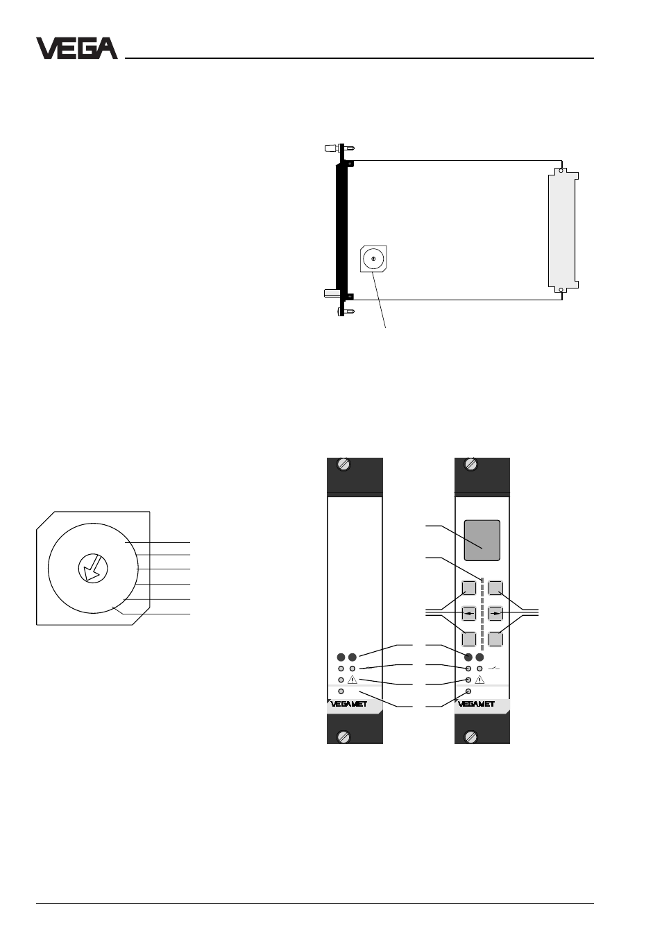
4.1 Indicating and adjustment
elements
A rotary switch is located on the circuit
board. It is used for adjustment of the instru-
ment address on DISBUS. This setting is
necessary if measured values are to be
transmitted via the DISBUS cable to external
instruments, e.g. VEGADIS 174 indicating
instrument, VEGACOM 557 interface con-
verter or other VEGAMETs. With these exter-
nal instruments, a received measured value
can be associated with a specific measure-
ment loop by means of the address.
The adjustment range 1 … F corresponds to
the DISBUS addresses 1 … 15.
Factory setting: 1
Note:
With address 0, the VEGAMET does not
participate in the DISBUS communication.
Rotary switch
Adjustment
The set instrument address on the DISBUS
can be indicated via the LC display.
Note
If several VEGAMET are linked via the
DISBUS, each address must be assigned
only once!
8
7
6
5
4
0
F
E
D
C
B
A
9
3 3
2
1
10
11
12
13
14
15
Front plate VEGAMET 515V
without adjustment
with adjustment
module 515VN
module 515V
1 LCD (4 lines with 6 figures each, illuminated) for clear text
indication
2 LED chain (yellow) for quasianalogue indication of the
measured value
3 Keys for menu adjustment
4 Connection socket for VEGACONNECT
5 LED (yellow) lights if the relay is energised (standard
setting)
6 LED (red), lights if fail safe relay is deenergised
7 LED (green), lights if operating voltage is on
Rotary switch
CONNECT
%
100
+
-
OK
ESC
on
1
2
514
CONNECT
%
100
+
-
OK
ESC
on
1
2
515V
CONNECT
on
1
2
515V
1
2
3
3
4
5
6
7
Position of the rotary switch