3 electrical connection, 1 connection instructions, 2 wiring plan – VEGA VEGAMET 515V User Manual
Page 11: Electrical connection
VEGAMET 515V
11
Electrical connection
3 Electrical connection
3.1 Connection instructions
Note the following instructions for electrical
connection:
- The connection must be made acc. to the
local installation standards (e.g. in Ger-
many acc. to the VDE-regulations).
- The wiring between VEGAMET and sensor
can be done with standard two-wire cable.
- If strong electromagnetic interference is
expected, screened cable is recom-
mended. The screening must be earthed
on both ends.
- The line resistances stated in the technical
data must not be exceeded.
- If overvoltages are expected, we recom-
mend a sensor electronics with integrated
overvoltage protection or the installation of
VEGA overvoltage arresters.
- The voltage supply of VEGAMET must
provide extra-low voltage to ensure pro-
tection class II. When using VEGASTAB
593, a reliable separation from the mains
circuits acc. to DIN VDE 0106, part 101 is
ensured.
2
28
24
22
30
32
d b z
+
–
+
–
+
–
–
+
–
+
–
+
+
–
+
–
L (+)
N (–)
6
10
12
2
3
–
+
–
+
1
20
16
18
+
–
+
+
+
Note:
Terminals d30 and z30 or d32 and z32 are
switched in parallel in the signal conditioning
instrument.
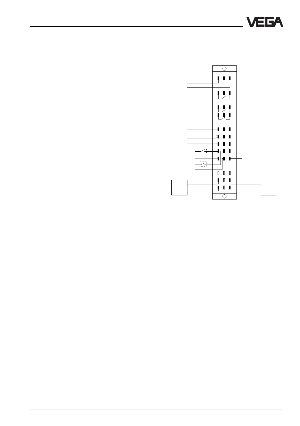
3.2 Wiring plan
Supply
voltage
Fail safe relay
Level relay 1
Sensor 1
Sensor 2
DISBUS output
Current outputs 1 … 3
Voltage outputs 1 … 3
Correction signal
Input 4
Correction signal
Input 5
Level relay 2