Installation guide, Installation, Configuration – Veris Industries H8920-1 Install User Manual
Page 3
Z202806-0H
PAGE 3
©2011 Veris Industries USA 800.354.8556 or +1.503.598.4564 / [email protected]
07111
Alta Labs, Enercept, Enspector, Hawkeye, Trustat, Veris, and the Veris ‘V’ logo are trademarks or registered trademarks of Veris Industries, L.L.C. in the USA and/or other countries.
TM
H8920-1
INSTALLATION GUIDE
INSTALLATION
1. Remove screws from the lid of the H8920-1 housing. Lift lid and remove wire guide
caps. Set aside with the lid.
2. Bring the H8036 RS-485 network cable to the
Modbus terminal block marked +MB-. Thread
wires through wire guide before terminating.
Connect the (+) to TB6. Connect the (-) wire to
TB5. Connect the shield wire to TB4.
3. Bring the LON Works network cable to the
terminal block marked BA LON. Thread wires
through wire guide before terminating. Connect
the A wire to TB1. Connect the B wire to TB2.
Connect the LON network shield wire to TB3.
4. Connect the 16-24 VAC/DC power wires to TB7 and TB8. The power terminals are
not polarity sensitive. This power source must be separate and isolated from other
circuits to prevent unwanted "ground loops."*
5. Thread wires through the most convenient openings in the housing.
6. Re-attach the lid and snap wire guides into place. Replace screws to hold the
housing together.
7. Mount the H8920-1. The device can be flush mounted to a wall, screw mounted to
a 2 or 4s electrical encosure, or nipple mounted to an existing enclosure. Mount
the H8920-1 in a class 2 environment.
8. Refer to the H8036 installation instructions for connection of the LON node to the
H8036 power meter.
* Veris transformers such as X020xxx, X040xxx or X050xxx or DC power supplies such as PS-24-7.5,
15, or 30 fulfill these requirements. If the installation only has non-isolated 24 VAC available, then
a Veris transformer such as X020ADA can provide the necessary isolation.
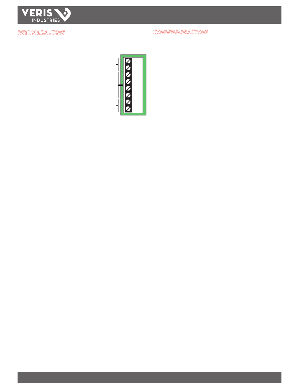
LON A
LON B
Modbus –
Modbus +
Power
TB1
TB2
TB3
TB4
TB5
TB6
TB7
TB8
Shield
CONFIGURATION
1. Upon powering up, the OP-LED is lit.
2. During operation, the OP-LED turns off if either of the following occurs:
a) No Modbus requests are generated by the unit for 10 seconds. This occurs
with new units (which have yet to be commissioned) or any units which
are in "Unconfigured," "Off-Line" or "Disabled" LonTalk states. Under these
conditions, the neuron chip will not generate requests to the Modbus
network.
b) No response or an error response from the Modbus network (e.g. no meter
attached, wrong type of meter (H8035 instead of H8036), broken RS-485
wires, etc.).
3. If the OP-LED is OFF for any reason covered in step 2 above, it will be re-lit when a
correct response is received from the Modbus network.
4. Under Condition 2b above, the floating-point SNVT data will be replaced with
floating-point-not-a-number (NaN,0x7FC00000), indicating to the remote user
that the data is no longer valid.
Index Feature
By adjusting the network input variable nviMeter Index, the Modbus address used to
populate all of the NVOs can be changed. This option is used to view and archive
data from a Modbus network of up to 63 H8036 power meters. Using this feature
eliminates the possibility of binding any points from the node. If the application
requires binding, the LON node can only view one meter.
Using the Meter-Index function
To ensure that the data read from the unit corresponds to the correct meter, follow
this algorithm:
1. Change nviMeter Index to the desired meter.
2. Wait for nvoMeter Index to change to the same value as nviMeter Index. Do
not read data from the unit until this occurs: You will not be able to determine
which meter the data corresponds to until nvoMeter Index=nviMeter Index.
Do not use "time-delays" to wait for the new data to be valid.
3. Once nvoMeter Index=nviMeter Index, you may poll values with the
assurance that the data corresponds to the desired meter.
Power Meter Configuration
If binding is required, use Modbus address 1 for the H8036 power meter. When
employing the indexing method, use addresses 1-63. Please refer to the H8036
Installation Instructions for meter addressing information.
Auto Propagate Feature
The H8920-1 automatically propagates all network variables. If nciMaxSendTg is
set above zero (default is zero), all variables are propagated periodically. Units are
in tenths of a second. For example, if nciMaxSendTg is set to 100, the H8920-1 will
automatically propagate all variables every 10 seconds.