Installation, Service, Power connection – Veris Industries H663 SERIES Install User Manual
Page 7: Changing the lithium battery
-7-
Z202833-0K
©2006 Veris Industries
10061
2. Use Software Configuration Tool to set up breaker size, warning levels, and alarm levels.
3. Power Connection
Disconnect and lock out power source before making any connections. Connect 2-wire 120 VAC power to
power terminals. (see #5 on page 2 for location) Observe polarity.
Changing the Lithium Battery
1. Normal life expectancy is approximately 5 years.
2. Disconnect and lock out power to panel.
3. Disconnect and lock out 120 V* power source to Data Acquisition Board.
4. Remove old lithium battery. Take care not to short battery terminals.
5. Replace with new lithium battery. (See specifications for battery type)
6. Reconnect 120V* power source to Data Acquisition Board.
7. Reconnect power.
Note: Do not dispose of lithium battery in fire. Use local recycling facility to dispose of lithium batteries.
Changing the Fuse
1. Disconnect and lock out power.
2. Disconnect and lock out 120V* power source to Data Acquisition Board.
3. Remove old fuse.
4. Replace with new fuse (see specifications for fuse type).
5. Reconnect 120V* power source to Data Acquisition Board.
6. Reconnect power.
7. Check “Alive” LED for proper function (See Figure 1, #3 on page 2 for location).
*240VAC for H663SM-
xxE
**If fuse blows repeatedly, check power source to ensure that it is a stable 120VAC source.
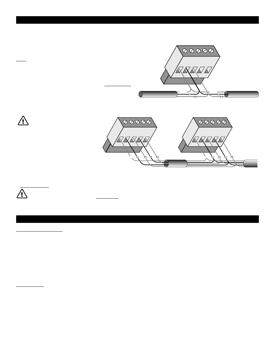
Master (Network Display)
Slave (H663 series)
TX+
SHLD
TX+
RX+
TX–
RX–
TX–
TX+
SHLD
TX+
RX+
TX–
RX–
TX–
SHIELD
SHIELD
Master or Slave
TX+
SHLD
TX+
RX+
TX–
RX–
TX–
SHIELD
SHIELD
INSTALLATION
NOTES
A. The Modbus cable should be mechanically secured where it enters the
electrical panel.
B. All Modbus devices should be connected together in a daisy-chain fashion,
and properly terminated.
C. The Modbus cable should be shielded twisted pair wire such as Belden 1120A.
The cable must be voltage rated for the installation.
WARNING: After wiring the
Modbus cable, remove all scraps
of wire or foil shield from the
electrical panel. This could be
DANGEROUS if wire scraps
come into contact with
high voltage conductors!
2-Wire
4-Wire
Figure 4
1. Connect 2-wire or 4-wire Modbus RS485 network (see Figure 4).
SERVICE