Installation, Physical installation – Veris Industries H663 SERIES Install User Manual
Page 3
-3-
-3-
Z202833-0K
©2006 Veris Industries
10061
INSTALLATION
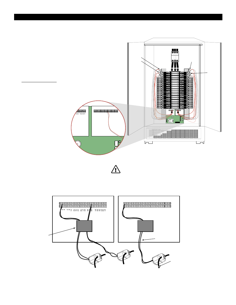
Physical Installation
1. Snap split-core CT’s on branch circuit wires. (CT’s may need to be staggered).
2. Prepare 120VAC* 50/60Hz power leads and connect to line and neutral
terminals of the acquisition board. Allow wiring length to fit when board is
installed. DO NOT CONNECT LINE VOLTAGE UNTIL LAST STEP!
3. Connect current transformers to interconnection board terminals as shown in
Figure 3.
4. Acquisition Board Installation (see Figure 2)
Find screw holes under panel board in side of chassis or panel. Attach
Data Acquisition Board.
Figure 2
Panel Board 1
20
20
20
20
20
20
20
20
20
20
20
20
20
20
20
20
20
20
20
20
20
20
20
20
20
20
20
20
20
20
20
20
20
20
20
20
20
20
20
20
LEFT
RIGHT
4
1
3
9
3
7
3
5
3
3
3
1
2
9
2
7
2
5
2
3
2
1
1
9
1
7
1
5
1
3
1
1
9
7
5
3
1
4
2
4
0
3
8
3
6
3
4
3
2
3
0
2
8
2
6
2
4
2
2
2
0
1
8
1
6
1
4
1
2
1
0
8
6
4
2
Channel 4
Channel 2
Channel 3
Channel 41
Channel 1
FT
RIGHT
"
"
"
"
"
"
"
"
"
"
Channel 42
"
"
"
"
"
"
"
"
"
"
6
4
2
12
10
8
18
16
14
24
22
20
30
28
26
36
34
32
42
40
38
DANGER: Beware of exposed busbars on back of panelboard when installing circuit board
assembly/mounting bracket. Assure adequate clearance between live parts and this product.
LEFT
RIGHT
Velcro Strap
holds cable
wire in place
Branch circuit wire
6' Lead
6
4
2
12
10
8
18
16
14
24
22
20
30
28
26
36
34
32
42
40
38
Figure 3
*240VAC for H663SM-
xxE