Allocate a relay channel to control the fan, Velleman – Velleman VMB1TC User Manual
Page 18
18
VMB1TC Temperature controller manual – rev 5.0
Allocate a relay channel to control the fan
In our example, the fan of the convector must be switched on when the temperature measured by the third temperature
sensor deviates too much from the desired value. The fan is steered by relay channel 2 of the second relay module.
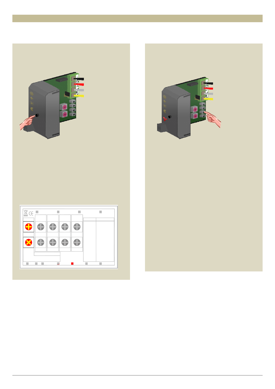
1. Set the third sensor module in anti-freeze mode by
pressing the push button on the front panel
repeatedly until all LEDs are off.
2. Set the MODE and TIME1 rotary switches for
channel 2 of the second relay module to ‘0’ (instant
control).
3. Remember the address of this relay module to
reinstate it later on.
4. Set the address of the second relay module to ‘C2’.
The ‘MODE 2’ LED flashes to indicate push button
learning mode (PBM).
Mode/
F
9
Time2
F
9
C
AB
D
E
4
5
67
8
3
0 1
2
9
F
ADDR.
E
D
C
B A
3
2
D
E
4
5
8
7 6
AB
C
1
0
2
3
5
4
67
8
0 1
Mode/Time2
Trig Release
Turn On Delay
Non-Retrigger
Turn Off Delay
4 Channel relay module
Mode4
30'
A:30'
Mode1
Ax
Bx
CH1
Rx
ON
Learn
Fx
Ex
Dx
Cx
: ON
PBM
TGL
:
:
OFF
:
Tx
CH2
x=CH1...4
TG1
TG2
:
:
ST2
ST1
:
8x
9x :
B:1h
C:2h
F:Toggle
E:1day
D:5h
Mode2
VMB4RY
velleman
CH3
CH4
Mode3
5h
Toggle
1day
1h
2h
Time1
Time2
Mode/
Out2
Time1
Time2
Mode/
ADDR.
Time1
Time2
Mode/
Out1
Time1
2:10s
3:15s
5:1'
6:2'
4:30s
0:Moment
1:5s
8:10'
9:15'
7:5'
Time1
Time2
Mode/
Blink
10'
15'
5'
Start-stop
Staircase
Out3
Out4
9
F
E
D
C
B A
3
2
4
5
8
7 6
1
0
9
F
E
D
C
B A
3
2
4
5
8
7 6
1
0
9
F
E
D
C
B A
3
2
4
5
8
7 6
1
0
9
F
E
D
C
B A
3
2
4
5
8
7 6
1
0
F
9
D
AB
C
E
3
5
4
67
8
0
1 2
F
9
D
AB
C
E
3
5
4
67
8
0 1 2
F
9
D
AB
C
E
3
5
4
67
8
0 1 2
5. Press and hold the second push button (TURBO) of
the third temperature sensor until the relay is
energised and the red LED on the sensor module
flashes.
6. Set the address of the second relay module back to
its original value.