Vmb1ts manual – edition 2 25, Velleman – Velleman VMB1TS User Manual
Page 25
VMB1TS manual – edition 2
25
Allocate a relay channel for the high temperature alarm
The sensor module can also control a relay when room temperature should reach extreme high values. This situation
might occur when a heating valve is broken e.g. it does not close anymore causing the room to keep heating up. The
relay contact can than be used e.g. to switch on a warning light or activate an audible warning signal.
As an example, relay channel 3 of a relay module is used.
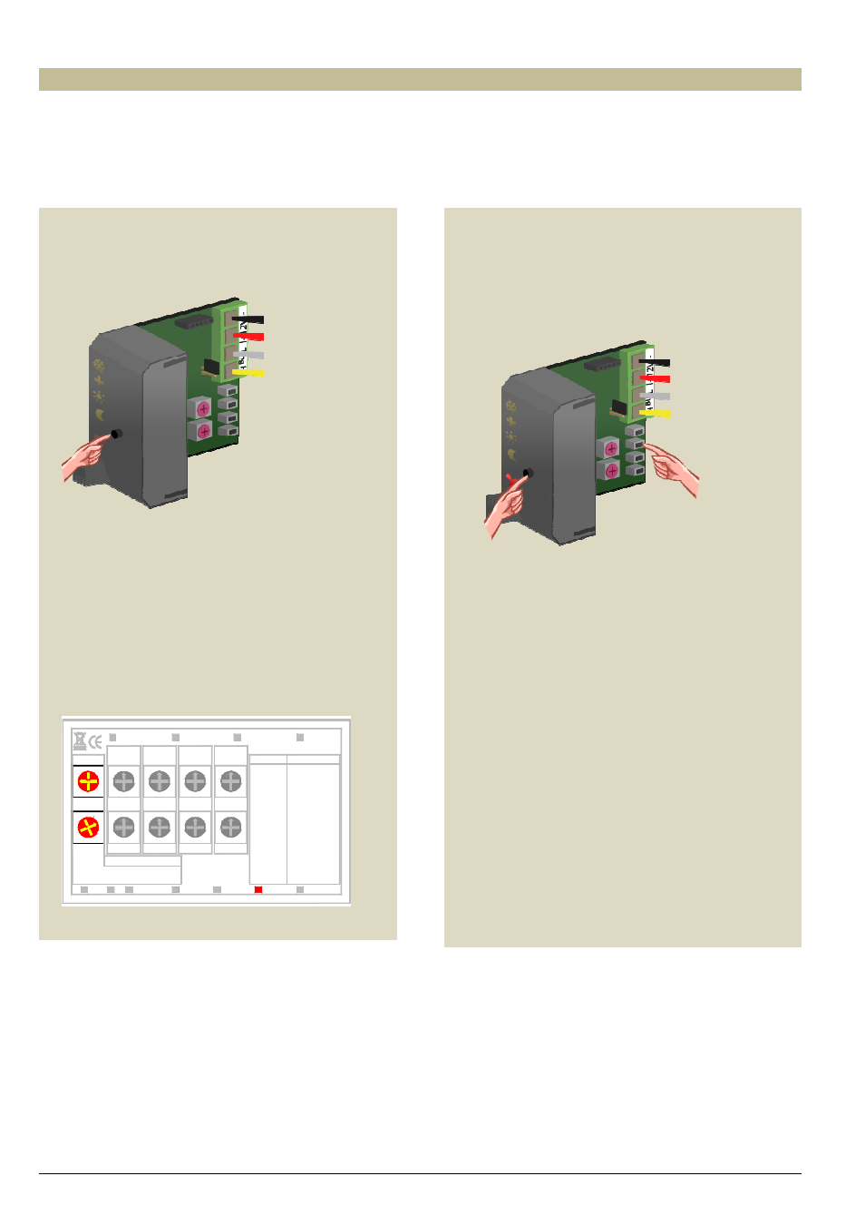
1. Set the sensor module in anti-freeze mode by
pressing the push button on the front panel
repeatedly until all LEDs are off.
2. Set the MODE and TIME1 rotary switches for
channel 3 of the relay module to ‘0’ (instant
control).
3. Remember the address of this relay module to
reinstate it later on.
4. Set the address of the relay module to ‘C3’. The
‘MODE 3’ LED flashes to indicate push button
learning mode (PBM).
Mode/
F
9
Time2
F
9
C
AB
D
E
4
5
67
8
3
0 12
9
F
ADDR.
E
D
C
B
A
3
2
D
E
4
5
8
7
6
A
B
C
1
0
2
3
5
4
67
8
0 1
Mode/Time2
Trig Release
Turn On Delay
Non-Retrigger
Turn Off Delay
4 Channel relay module
Mode4
30'
A:30'
Mode1
Ax
Bx
CH1
Rx
ON
Learn
Fx
Ex
Dx
Cx
:ON
PBM
TGL
:
:
OFF
:
Tx
CH2
x=CH1...4
TG1
TG2
:
:
ST2
ST1
:
8x
9x :
B:1h
C:2h
F:Toggle
E:1day
D:5h
Mode2
VMB4RY
velleman
CH3
CH4
Mode3
5h
Toggle
1day
1h
2h
Time1
Time2
Mode/
Out2
Time1
Time2
Mode/
ADDR.
Time1
Time2
Mode/
Out1
Time1
2:10s
3:15s
5:1'
6:2'
4:30s
0:Moment
1:5s
8:10'
9:15'
7:5'
Time1
Time2
Mode/
Blink
10'
15'
5'
Start-stop
Staircase
Out3
Out4
9
F
E
D
C
B
A
3
2
4
5
8
7
6
1
0
9
F
E
D
C
B
A
3
2
4
5
8
7
6
1
0
9
F
E
D
C
B
A
3
2
4
5
8
7
6
1
0
9
F
E
D
C
B A
3
2
4
5
8
7
6
1
0
F
9
D
AB
C
E
3
5
4
67
8
0 12
F
9
D
AB
C
E
3
5
4
67
8
0
1 2
F
9
D
AB
C
E
3
5
4
67
8
0 1 2
5. Press and hold the pushbutton on the front panel of
the sensor module and simultaneously press and
hold the third push button (DAY) until the relay is
energised and the red LED on the sensor module
flashes. First release the third push button (DAY)
followed by the push button on the front panel.
6. Set the address of the relay module back to its
original value.