Terminator, Addressing – Velleman VMB1TS User Manual
Page 13
VMB1TS manual – edition 2
13
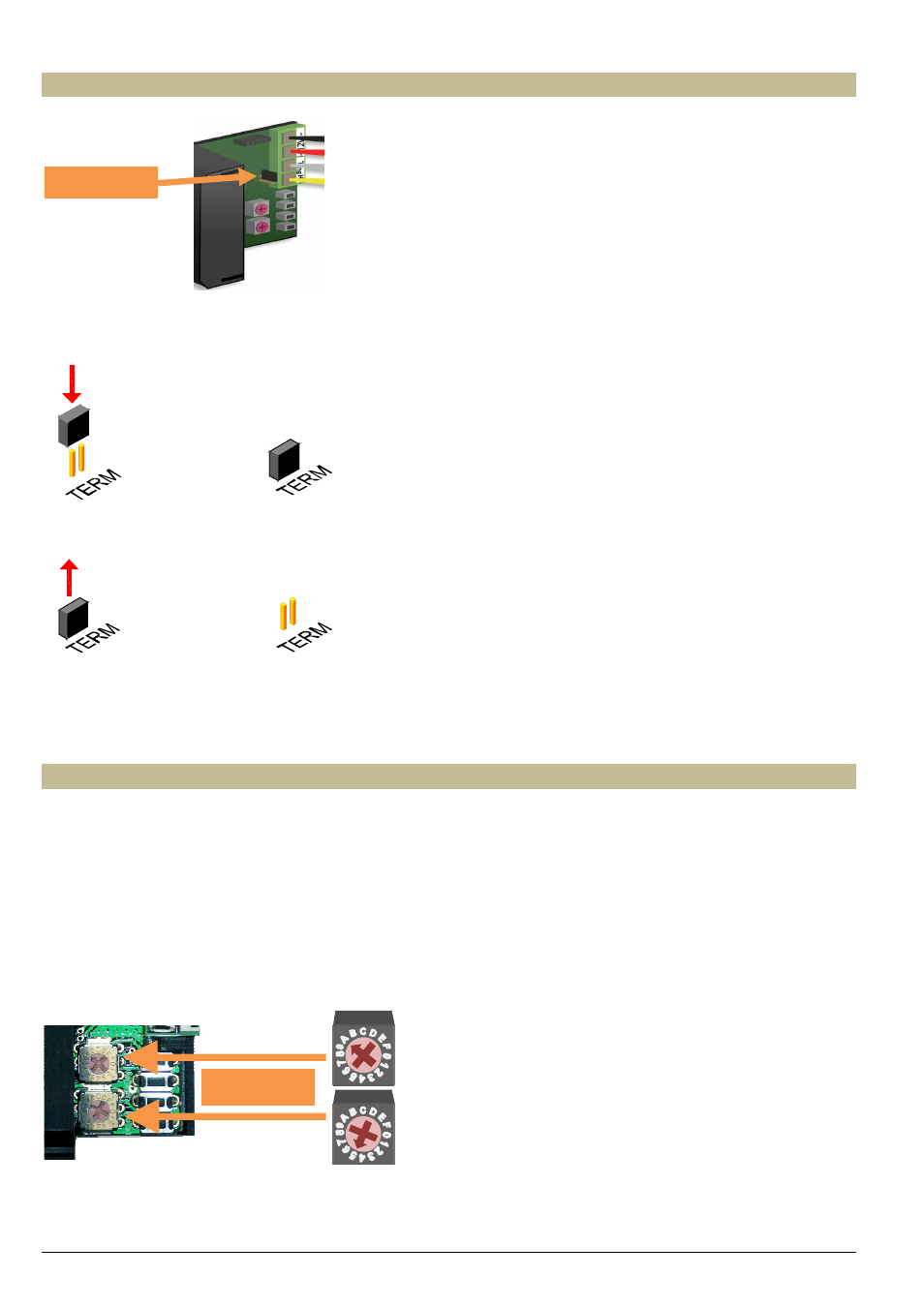
Terminator
Normally only 2 ‘TERM’ terminators must be used in a complete Velbus installation. Usually this will be on one
module inside the distribution box and on the module which is physically located furthest from the distribution box.
On all other modules, the terminator must be removed.
Remark:
In case the wiring contains a lot of branches, still only one terminator is placed on one module inside the distribution
box and one on the module which is physically located furthest from the distribution box. When communication errors
occur, an additional terminator can be used at the end of another branch. However, the number of terminators should
be limited as more terminators place a heavy load on the bus.
Addressing
Every module on the Velbus system must have its own unique address.
On modules with a rotary switch e.g. the temperature sensor VMB1TS and the relay module VMB4RY the address is
set using the ‘ADDR’ rotary switch (also refer to the manual of the relevant module).
The address of the temperature controller VMB1TC is set via a menu (refer to the manual of the temperature
controller).
These addresses may not be altered afterwards.
Set a unique Velbus address for the temperature using the ‘ADDR’ rotary switches, from ‘00’ to ‘FE’, except the
reserved addresses: ‘81’, ‘91’, ‘A1’, 'B1', ‘C1’, ‘D1’, ‘E1’, ‘F1’ en ‘FF’.
The example below shows the setting for address ‘A5’.
ADDR = A5
Terminator