Data sheet, Standard variant 8.06, Shaft assembly – Spicer SERVICE CATALOG User Manual
Page 9: With length compensation, Design
7
© Dana Spicer
All applications must be approved by Dana. Specifications and/or design are subject to change without notice or obligation.
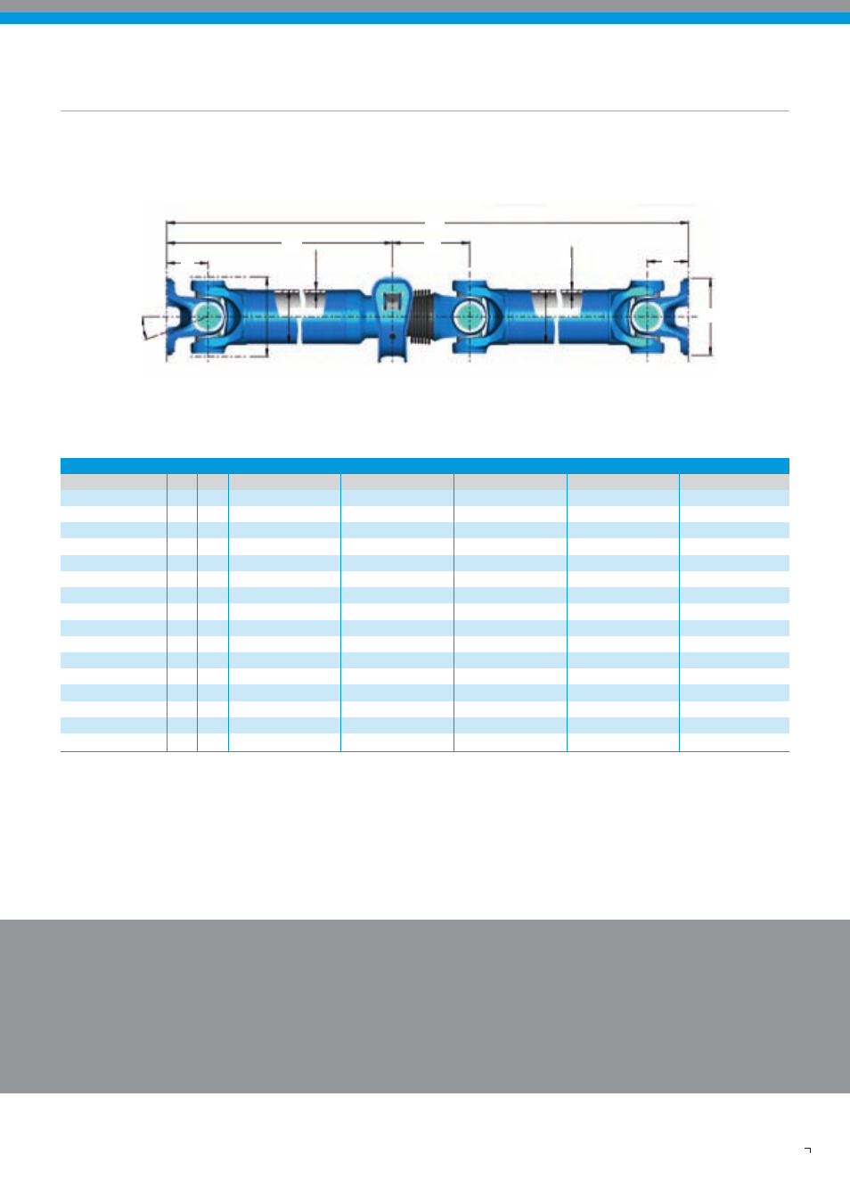
Data Sheet
Standard Variant 8.06
Shaft Assembly
with length compensation
in midship bearing area
Recommended connection
Companion flanges
- XS : Cross serration according to ISO 8667
Driveshaft flange yokes
- XS : Cross serration according to ISO 12667
Please note:
All values given are nominal. Exact information
should only be obtained from drawing.
* Optional 193,5
Design
β
K
S
D
D
S
M
L
1
L
z
Q
A
M
Compact
2030 2035 2040 2045 2055
Funktional limit torque
T
cs
kNm
6,5 10,0 14,0 17,0 25,0
Connection
-
KV 120
KV 150
KV 150
KV 180
KV 180
Flange-ø A
120 155 155 180 180
Max. Joint angle
ß mm
25
25
25
25
25
Max. Rotation-ø
K °
127
144
160
174
178
Standout
M mm
63,5
75
82
87
92
Compressed length
L
z min.
mm
632
720
765
816
863
lenght 1
L
1 min.
mm
266,5
318
308
330
352
Sliding movement
L
a
mm
110
110
110
110
110
Tube
D x S
mm
90 x 3
100 x 3
120 x 3
120 x 4
120 x 6
Joint overhang
Q
min.
kg
142
146
156
164
174
Hole distance
X kg
220* 220* 220 220 220
Drop height N
mm
90 90 90 90 90
Hole-ø d
kg
15 15 15 15 15
Weight of 2m-shaft
G
W
kg 32,3
39,8
50,6
66,1
76,2
Weight of 1m-tube
G
R
kg 6,4
7,2
8,7
11,4
16,9