Data sheet, Standard variant 0.06, Driveshaft – Spicer SERVICE CATALOG User Manual
Page 12
10
© Dana Spicer
Data Sheet
Standard Variant 0.06
Driveshaft
with length compensation and centred double joint on both sides
Design
Recommended connection
Companion flanges
- DIN:
according to ISO 7646
- SAE:
according to ISO 7647
- XS :
Cross serration according to ISO 8667
Driveshaft flange yokes
- XS : Cross serration according to ISO 12667
Please note:
All values given are nominal. Exact information
should only be obtained from drawing.
Attention:
Not all DIN/SAE-flange-connection can transmit
the function-limit-torque of the corresponding
driveshaft size by friction.
100
50
0
0
10
20
30
40
To
rq
ue
%
Deflection angle
β
[ °]
All applications must be approved by Dana. Specifications and/or design are subject to change without notice or obligation.
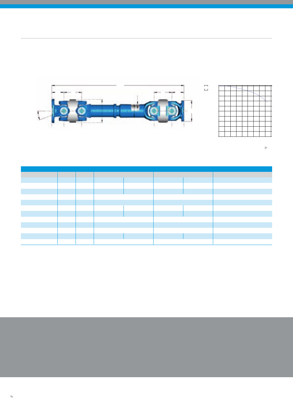
S
β
M
Z
Z
M
Lz
A
D
K
Transmission capacity dependent on deflection
angle for a centred double joint
Compact
687.30 587.20 587.35
Funktional limit torque
T
cs
kNm
3,9 6,5 7,4 8,3
17,0
Connection
-
DIN 120
DIN 150
DIN 150
KV 150
DIN 180
Flange-ø
A mm
120
150
150
155
180
Max. Joint angle
ß
°
42
20/42
20/42
Max. Rotation-ø
K mm
140
152
182
Standout
M mm
72
70
75
78
90
Compressed length
L
z min.
mm
829
825
797
803
1040
Sliding movement
L
a
mm
190
110
150
Standout
Z mm
102
115
140
Tube
D x S
mm
90 x 3
85 x 5
100 x 6
Weight of 1m-shaft
G
W
kg
36,1 kg
37,0 kg
40,2
41,0
75
Weight of 1m-tube
G
R
kg
6,4
9,9
13,9