Data sheet, Standard variant 9.01, Short coupled driveshaft – Spicer SERVICE CATALOG User Manual
Page 10: Sleeve-muff-design, Design
8
© Dana Spicer
Data Sheet
Standard Variant 9.01
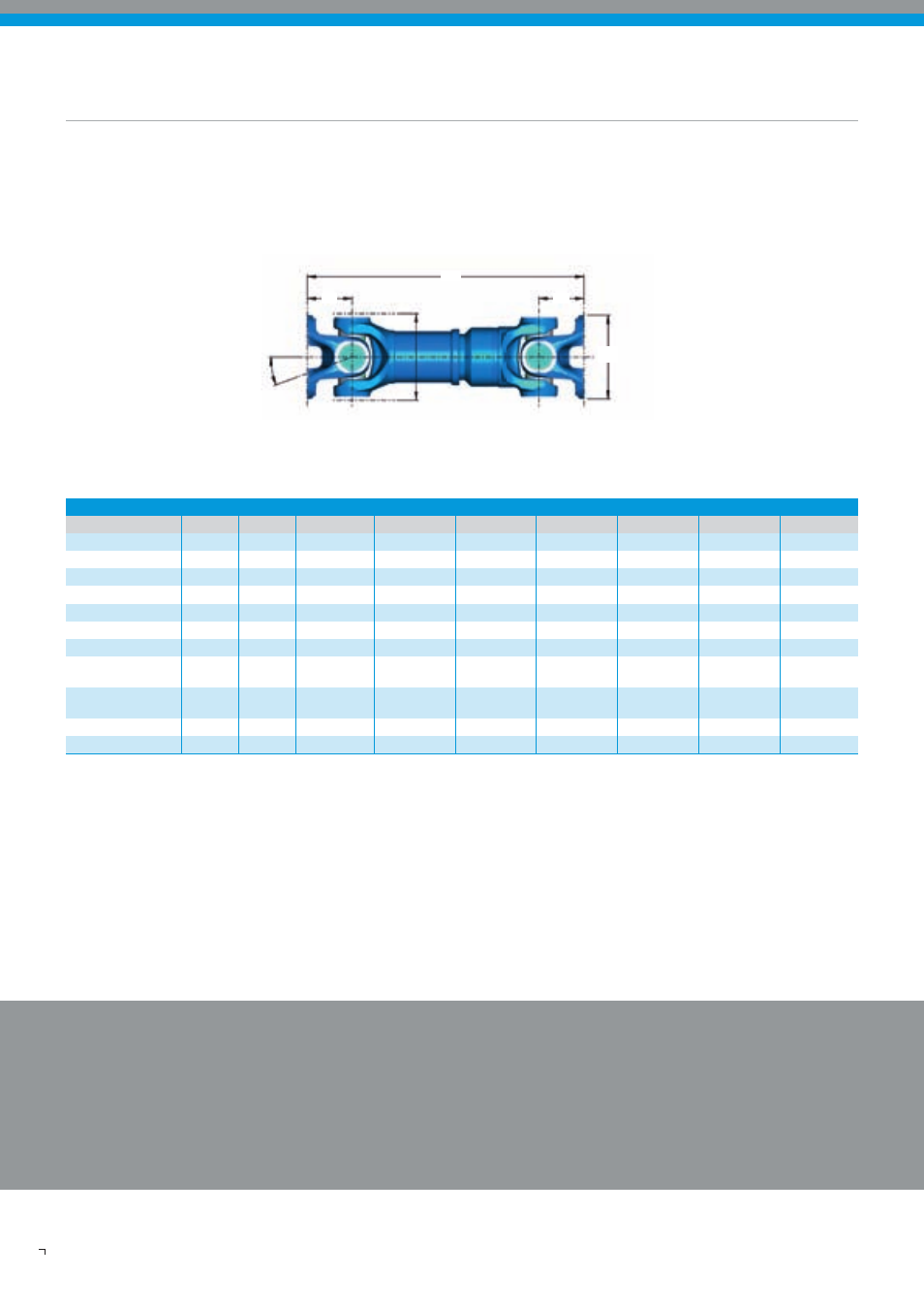
Short Coupled Driveshaft
Sleeve-Muff-Design
Recommended connection
Companion flanges
- XS : Cross serration according to ISO 8667
Driveshaft flange yokes
- XS : Cross serration according to ISO 12667
Please note:
All values given are nominal. Exact information
should only be obtained from drawing.
Design
All applications must be approved by Dana. Specifications and/or design are subject to change without notice or obligation.
K
L
Z
M
β
M
A
Compact
2030 2035 2040 2045 2055 2060 2065
Funktional limit torque
T
cs
kNm
6,5 10,0 14,0 17,0 25,0 30,0 35,0
Connection
-
KV 120
KV 150
KV 150
KV 180
KV 180
KV180
KV 180
Optional
KV 150
KV 120
KV 180
KV 150
Flange-ø
A
mm
120 120 155 180 180 180 180
Max. Joint angle
ß
°
25 25 25 25 25 25 25
Max. Rotation-ø
K mm 127
144
160
174
178
196
206
Standout
M
mm
63,5
75 82 87 92 100 105
Compressed length/
L
z max./
L
a
mm/mm
436/110
510/110
505/110
541/110
571/110
590/110
631/110
Sliding movement
Compressed length/
L
z max./
L
a
mm/mm
371/45
470/70
465/70
501/70
541/70
550/70
591/70
Sliding movement
Max. Weight
G
W max.
kg
15,2
20,5
23,5
31,4
39,7
46,0
61,1
Min. Weight
G
W min.
mm
13,5
19,3
21,7
29,4
36,8
43,6
57,9