Carrier removal (diff. lock), Carrier remov, Carrier remov carrier removal al al al al – Spicer Drive Axles Service Manual Wheel Reduction Drive Axles (EA-50) User Manual
Page 29
27
CARRIER REMOV
CARRIER REMOV
CARRIER REMOV
CARRIER REMOV
CARRIER REMOVAL
AL
AL
AL
AL
NO
NO
NO
NO
NOTE: Contin
TE: Contin
TE: Contin
TE: Contin
TE: Continue t
ue t
ue t
ue t
ue to k
o k
o k
o k
o keep differ
eep differ
eep differ
eep differ
eep differential lock engaged
ential lock engaged
ential lock engaged
ential lock engaged
ential lock engaged
(lock
(lock
(lock
(lock
(locked) with air pr
ed) with air pr
ed) with air pr
ed) with air pr
ed) with air preeeeessur
ssur
ssur
ssur
ssure until carrier ha
e until carrier ha
e until carrier ha
e until carrier ha
e until carrier has been
s been
s been
s been
s been
comple
comple
comple
comple
completttttel
el
el
el
ely r
y r
y r
y r
y remo
emo
emo
emo
emovvvvved fr
ed fr
ed fr
ed fr
ed from the axle housing.
om the axle housing.
om the axle housing.
om the axle housing.
om the axle housing.
9. Remove the axle shafts and carrier assembly from the
axle housing using the procedures as shown on
Page 8.
10.When carrier has been removed from the axle
housing, remove auxiliary pressure from the shift
cylinder.
CARRIER REMOVAL
Before carrier assembly can be removed from the axle
housing, the main differential lock must be engaged (in
the locked position). This must be done before the right-
side axle shaft is removed. Engaging (locking) the main
differential allows enough clearance for the clutch collar
to clear the carrier-to-housing mounting flange so removal
can be achieved.
NO
NO
NO
NO
NOTE: Locking of the main differ
TE: Locking of the main differ
TE: Locking of the main differ
TE: Locking of the main differ
TE: Locking of the main differential m
ential m
ential m
ential m
ential must be done
ust be done
ust be done
ust be done
ust be done
befor
befor
befor
befor
before r
e r
e r
e r
e remo
emo
emo
emo
emoving the right
ving the right
ving the right
ving the right
ving the right-side axle shaft. If the right
-side axle shaft. If the right
-side axle shaft. If the right
-side axle shaft. If the right
-side axle shaft. If the right-----
side axle shaft w
side axle shaft w
side axle shaft w
side axle shaft w
side axle shaft waaaaas r
s r
s r
s r
s remo
emo
emo
emo
emovvvvved for t
ed for t
ed for t
ed for t
ed for to
oo
oowing purpose
wing purpose
wing purpose
wing purpose
wing purposes,
s,
s,
s,
s,
rrrrreinst
einst
einst
einst
einstall it int
all it int
all it int
all it int
all it into the housing using pr
o the housing using pr
o the housing using pr
o the housing using pr
o the housing using procedur
ocedur
ocedur
ocedur
ocedure 2. fr
e 2. fr
e 2. fr
e 2. fr
e 2. from
om
om
om
om
the "Inst
the "Inst
the "Inst
the "Inst
the "Install Axle Shaft
all Axle Shaft
all Axle Shaft
all Axle Shaft
all Axle Shafts Aft
s Aft
s Aft
s Aft
s After T
er T
er T
er T
er To
oo
oowing". P
wing". P
wing". P
wing". P
wing". Page 2
age 2
age 2
age 2
age 26.
6.
6.
6.
6.
AIR PRESSURE METHOD
1. Drain lubricant from the axle assembly.
2. Raise the right-side rear drive wheel off the floor
using a hoist or jack.
3. Hold the right-side of the vehicle in the raised
position by using a jack stand under the right-
side housing spring seat.
4. Disconnect the drive shaft from the input yoke.
5. Disconnect air line from the differential lock
shift cylinder.
6. Connect an auxiliary air supply to the differen-
tial lock shift cylinder.
NO
NO
NO
NO
NOTE: If an auxiliary air suppl
TE: If an auxiliary air suppl
TE: If an auxiliary air suppl
TE: If an auxiliary air suppl
TE: If an auxiliary air supply is no
y is no
y is no
y is no
y is not a
t a
t a
t a
t avvvvvailable con-
ailable con-
ailable con-
ailable con-
ailable con-
tin
tin
tin
tin
tinue t
ue t
ue t
ue t
ue to use the "Man
o use the "Man
o use the "Man
o use the "Man
o use the "Manual Engaging Me
ual Engaging Me
ual Engaging Me
ual Engaging Me
ual Engaging Method" t
thod" t
thod" t
thod" t
thod" to lock
o lock
o lock
o lock
o lock
the main differntial.
the main differntial.
the main differntial.
the main differntial.
the main differntial.
7. Apply and hold air pressure to the shift cylinder.
This will move the clutch collar inward and engage
splines with the differential case splines,
locking the assembly.
8. To ensure differential clutch collar and case half have
engaged completely, rotate the drive pinion or the
right-side wheel.
MANUAL ENGAGING METHOD
NO
NO
NO
NO
NOTE: Use this me
TE: Use this me
TE: Use this me
TE: Use this me
TE: Use this method if auxiliary air is una
thod if auxiliary air is una
thod if auxiliary air is una
thod if auxiliary air is una
thod if auxiliary air is unavvvvvailabe.
ailabe.
ailabe.
ailabe.
ailabe.
1. Follow air pressure engagemant method through
step 5.
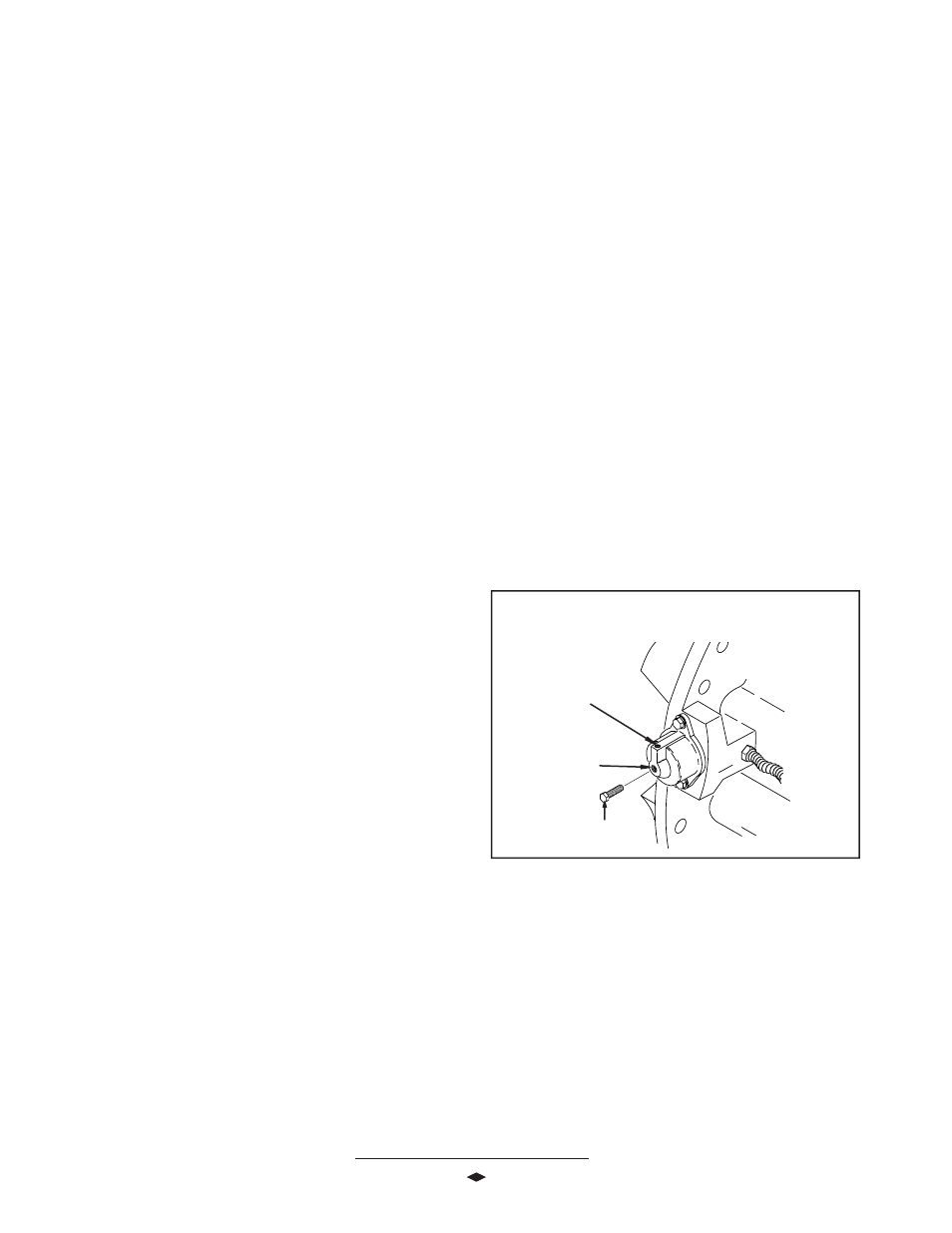
NO
NO
NO
NO
NOTE: R
TE: R
TE: R
TE: R
TE: Refer t
efer t
efer t
efer t
efer to F
o F
o F
o F
o Figur
igur
igur
igur
igure 1
e 1
e 1
e 1
e 14 for the follo
4 for the follo
4 for the follo
4 for the follo
4 for the following st
wing st
wing st
wing st
wing steps.
eps.
eps.
eps.
eps.
2. Remove plug from the hole in the center of the shift
cylinder cover.
3. Install an M12 x 1.50 bolt in the cylinder air-port,
same hole the plug was in, to manually engage the
differential.
Continued On Ne
Continued On Ne
Continued On Ne
Continued On Ne
Continued On Next P
xt P
xt P
xt P
xt Page
age
age
age
age
FFFFFigur
igur
igur
igur
igure 1
e 1
e 1
e 1
e 14
4
4
4
4
Air Supply
Air Supply
Air Supply
Air Supply
Air Supply
Inlet
Inlet
Inlet
Inlet
Inlet
Air Shift
Air Shift
Air Shift
Air Shift
Air Shift
C
C
C
C
Cylinder
ylinder
ylinder
ylinder
ylinder
Manual Eng
Manual Eng
Manual Eng
Manual Eng
Manual Engaging
aging
aging
aging
aging
M1
M1
M1
M1
M12 X 1.5
2 X 1.5
2 X 1.5
2 X 1.5
2 X 1.50 Bolt
0 Bolt
0 Bolt
0 Bolt
0 Bolt
DIFFERENTIAL LOCK
MANUAL ENGAGEMENT DIAGRAM