Differential installation, Differential inst – Spicer Drive Axles Service Manual Wheel Reduction Drive Axles (EA-50) User Manual
Page 22
20
DIFFERENTIAL INST
DIFFERENTIAL INST
DIFFERENTIAL INST
DIFFERENTIAL INST
DIFFERENTIAL INSTALLA
ALLA
ALLA
ALLA
ALLATION
TION
TION
TION
TION
1.
1.
1.
1.
1. Install ring gear and differential assembly into carrier
housing.
CA
CA
CA
CA
CAUTION: T
UTION: T
UTION: T
UTION: T
UTION: To a
o a
o a
o a
o avvvvvoid damage of ring gear and pinion,
oid damage of ring gear and pinion,
oid damage of ring gear and pinion,
oid damage of ring gear and pinion,
oid damage of ring gear and pinion,
car
car
car
car
care should be used when inst
e should be used when inst
e should be used when inst
e should be used when inst
e should be used when installing the ring gear
alling the ring gear
alling the ring gear
alling the ring gear
alling the ring gear
differ
differ
differ
differ
differential a
ential a
ential a
ential a
ential assembl
ssembl
ssembl
ssembl
ssembly int
y int
y int
y int
y into the carrier housing.
o the carrier housing.
o the carrier housing.
o the carrier housing.
o the carrier housing.
2.
2.
2.
2.
2. Be sure side bearing cups are seated on bearing
cones. Assemble differential bearing caps, with
match marks in proper location. Clean bearing cap
bolts and washers and coat threads with Loctite
#277. Install bearing cap bolts and tighten enough
to draw bolt head into contact with bearing cap,
eliminating visible space between differential bearing
cap and carrier housing. Do not torque the cap
bolts at this time.
4.
4.
4.
4.
4. Loosen adjusting ring on tooth side of ring gear one
notch and tighten adjusting ring on flange side of
ring gear one notch. Repeat process until backlash
is eliminated. Tighten adjusting ring on tooth side
of the ring gear until the ring gear and pinion
backlash matches the backlash etched on the
ring gear. This adjustment sets both the backlash
and the bearing preload.
5.
5.
5.
5.
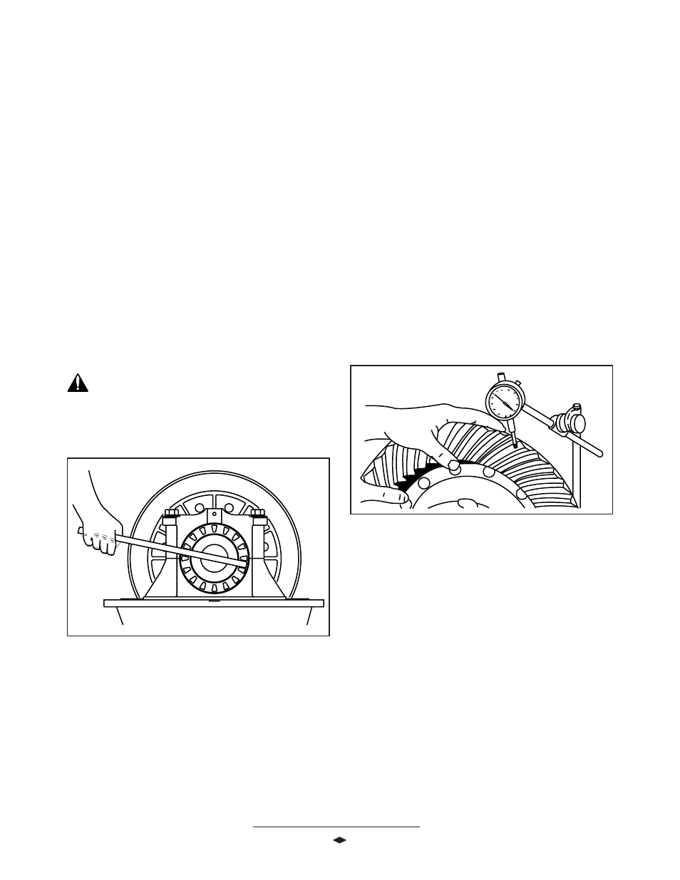
5. Check ring gear and pinion backlash in four equally
spaced positions around the ring gear with a dial
indicator as shown. See F
See F
See F
See F
See Figur
igur
igur
igur
igure 1
e 1
e 1
e 1
e 10. A
0. A
0. A
0. A
0. Accep
ccep
ccep
ccep
cceptttttable
able
able
able
able
backla
backla
backla
backla
backlash t
sh t
sh t
sh t
sh toler
oler
oler
oler
olerance is +/- .00
ance is +/- .00
ance is +/- .00
ance is +/- .00
ance is +/- .002" fr
2" fr
2" fr
2" fr
2" from backla
om backla
om backla
om backla
om backlash
sh
sh
sh
sh
eeeeetched on ring gear
tched on ring gear
tched on ring gear
tched on ring gear
tched on ring gear.....
FFFFFigur
igur
igur
igur
igure 1
e 1
e 1
e 1
e 10
0
0
0
0
NO
NO
NO
NO
NOTE: If the backla
TE: If the backla
TE: If the backla
TE: If the backla
TE: If the backlash t
sh t
sh t
sh t
sh toler
oler
oler
oler
olerance doe
ance doe
ance doe
ance doe
ance does no
s no
s no
s no
s not v
t v
t v
t v
t vary mor
ary mor
ary mor
ary mor
ary moreeeee
than .00
than .00
than .00
than .00
than .004 in. (.0
4 in. (.0
4 in. (.0
4 in. (.0
4 in. (.08
8
8
8
80 mm), the se
0 mm), the se
0 mm), the se
0 mm), the se
0 mm), the setttttting is accep
ting is accep
ting is accep
ting is accep
ting is acceptttttable. If
able. If
able. If
able. If
able. If
backla
backla
backla
backla
backlash doe
sh doe
sh doe
sh doe
sh does v
s v
s v
s v
s vary mor
ary mor
ary mor
ary mor
ary more than .00
e than .00
e than .00
e than .00
e than .004 in. (.0
4 in. (.0
4 in. (.0
4 in. (.0
4 in. (.08
8
8
8
80 mm),
0 mm),
0 mm),
0 mm),
0 mm),
rrrrremo
emo
emo
emo
emovvvvve the differ
e the differ
e the differ
e the differ
e the differential and de
ential and de
ential and de
ential and de
ential and detttttermine the cause.
ermine the cause.
ermine the cause.
ermine the cause.
ermine the cause.
6.
6.
6.
6.
6. Once backlash is set, torque the differential bearing
cap bolts to 295-340 Lb-Ft (397-460 N-m). Check
backlash after torquing cap bolts.
CA
CA
CA
CA
CAUTION:
UTION:
UTION:
UTION:
UTION: Differ
Differ
Differ
Differ
Differential a
ential a
ential a
ential a
ential assembl
ssembl
ssembl
ssembl
ssembly m
y m
y m
y m
y must be
ust be
ust be
ust be
ust be
aligned within bearing bor
aligned within bearing bor
aligned within bearing bor
aligned within bearing bor
aligned within bearing boreeeees befor
s befor
s befor
s befor
s before pr
e pr
e pr
e pr
e preload is applied
eload is applied
eload is applied
eload is applied
eload is applied
or damage t
or damage t
or damage t
or damage t
or damage to bearings can occur
o bearings can occur
o bearings can occur
o bearings can occur
o bearings can occur.....
FFFFFigur
igur
igur
igur
igure 9
e 9
e 9
e 9
e 9
3.
3.
3.
3.
3. Install adjusting rings. Tighten both adjusting rings
until end play is eliminated, and there is backlash
between the ring gear and pinion. See F
See F
See F
See F
See Figur
igur
igur
igur
igure 9.
e 9.
e 9.
e 9.
e 9.