2 rack mounting the instrument, 3 installing the sensor, Rack mounting the instrument – American Magnetics 187 Self-Compensating Liquid Level Controller User Manual
Page 19: Installing the sensor, Installation, Warning
8
Installation
Installing the sensor
2.2 Rack Mounting the Instrument
If the instrument has a rack mount chassis, follow the following procedure:
a. Attach the rack mount adapter pieces to the instrument by first
removing the four screws on the side of the instrument that
attach the cover to the chassis. Attach the rack mount adapter
pieces to the sides of the instrument by reinstalling the screws.
b. Install the instrument in a 19" rack by securing the front panel
to the rail in each of the four corners with mounting hardware
supplied by the cabinet manufacturer.
Warning
Do not remove the cabinet feet and then reinsert the original screws.
Doing so could present a severe life-threatening electrical hazard. If
removal of the cabinet feet is desired, replace the original screws
with screws not to exceed 1/4" in length. Screws longer than 1/4"
will contact and damage the printed circuit board inside the unit.
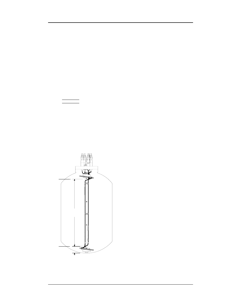
2.3 Installing the Sensor
Exercise care when installing the
sensor since dents, crimps, bends or
other physical distortions in the
cylindrical and plate sensors will
change electrical characteristics
and possibly cause calibration
errors and/or disruption of proper
instrument operation. It is also
important to ensure that the sensor
is installed in a vertical orientation
for optimal operation of the sensors.
Make a note of the 0% and 100%
points of the target vessel per
diagram at left. Before installing
the sensor and before filling the
target vessel, the user may first
want to review the Operation
section—especially the zero offset
and measured span length settings
discussed on page 14.
Drawings will be provided for
custom sensor or mounting flange
designs.
MAXIMUM
MEASURED
SPAN
MINIMUM
ZERO
OFFSET
100%
0%