2 calibration setup – American Magnetics 12100PS DC Power Supply (CE-Marked) User Manual
Page 50
CALIBRATION
OPERATING MANUAL
5-2
Release 2.0 (98/06)
5.2
Calibration Setup
5.2.3
Accessing Calibration Potentiometers
WARNING
Disconnect AC power from the unit before removing the cover. Even with
the front panel power switch in the OFF position, live line voltages are
exposed when the cover is removed. Repairs and adjustments must be
made by experienced service technicians only.
WARNING
Use a non-conducting, straight blade screwdriver to adjust the trim pots.
CAUTION
Follow established antistatic procedures. There are static-sensitive parts on
the printed circuit boards.
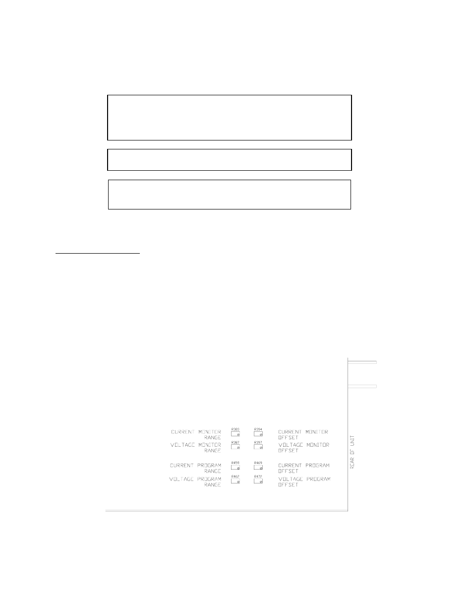
You will need to remove the power supply's cover to access the programming and readback calibration
potentiometers which are located on the A2 PCB. See Figure 5.2-1 to locate the potentiometers.
Removing Option Card
If there is a GPIB or RS-232 option card (PCB) installed inside the power supply, you will have to remove it to
access the calibration potentiometers.
Tool Required: Phillips #2 screwdriver
1. Turn off the power supply. Disconnect AC Power. Remove the cover.
2. Remove four screws from their standoffs inside the power supply to release the option card.
3. Remove two screws at the rear panel to release the option card's sub-plate.
4. Unplug the ribbon cable connectors from the option card. Lift out card.
Figure 5.2-1 Programming and Monitoring Calibration Locations
(Top view.)