American Magnetics 12100PS DC Power Supply (CE-Marked) User Manual
Page 43
REMOTE OPERATION
OPERATING MANUAL
4-2
Release 2.0 (98/06)
4.2.1
Rear Panel SW1 Switch (continued)
The rear panel SW1 switch is marked with the word OPEN on its upper surface. Any of the eight switches on
SW1 is OFF when it has been flipped up to break contact, ON when flipped down to close contact. Table 4.2-1
shows the functions assigned to each SW1 switch.
Table 4.2-1 Rear Panel SW1 Switch Assignments (Factory Defaults Underlined)
Switch
Function
Open
Closed
SW1-1
1mA current source for resistive programming
of output voltage
Voltage source
programming
Resistive programming
(0-5k, 0-10k)
SW1-2
1mA current source for resistive programming
of output current limit
Voltage source
programming
Resistive programming
(0-5k, 0-10k)
SW1-3
Output voltage programming source range
select
0-5V (0-5k)
0-10V (0-10k)
SW1-4
Output current limit programming source range
select
0-5V (0-5k)
0-10V (0-10k)
SW1-5
Output voltage monitor range select
0-5V
0-10V
SW1-6
Output current monitor range select
0-5V
0-10V
SW1-7
Remote shutdown logic select
HIGH=OFF
HIGH=ON
SW1-8
Over temperature shutdown reset mode select
Auto reset
Latch OFF
Resetting the Switches
Before making any changes to the switch settings, disable the power supply output by pushing the front panel
STANDBY switch to its IN position. This shuts down the power supply on a temporary basis. The front panel
S/D LED turns on. Then use any small, flat-bladed screwdriver to change the switch settings.
4.2.2
Rear Panel J2 Connector
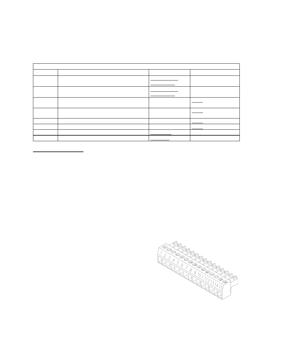
The J2 Programming and Monitoring connector is a 15-terminal wire clamp connector located on the power
supply's rear panel. See Figure 4.2-2. The J2 connector provides access to the following functions:
N
Remote programming of output voltage AND/OR current limit
N
Remote monitoring of calibrated readback signals for output voltage and output current
N
Remote control of the shutdown function using TTL-compatible signals
Figure 4.2-2 Programming and Monitoring J2 Connector
1 Remote Output Voltage Programming Select
2 Remote Output Current Limit Programming
Select
3 Control Ground
4 N/C
5 Voltage Program Signal Return
6 Output Voltage Programming Input
7 Current Program Signal Return
8 Output Current Limit Programming Input
9 Voltage Monitor Signal Return
10 Output Voltage Monitor
11 Current Monitor Signal Return
12 Output Current Monitor
13 N/C
14 TTL Shutdown (S/D) Signal Return (-)
15 TTL S/D Input (+)