American Magnetics 12100PS DC Power Supply (CE-Marked) User Manual
Page 41
OPERATING MANUAL
LOCAL OPERATION
Release 2.0 (98/06)
3-11
3.7.3
Troubleshooting for Operators
Use the checks in Table 3.7-1 to ensure the
power supply is configured and connected for default operation at
the front panel. If you need any further troubleshooting, call your service technician.
Abbreviated References Used in Table
ACF
AC fail
OTP
over temperature protection
OVP
over voltage protection
PCB
printed circuit board
PFC
power factor correction
REM
remote mode
S/D
shutdown
V
volts
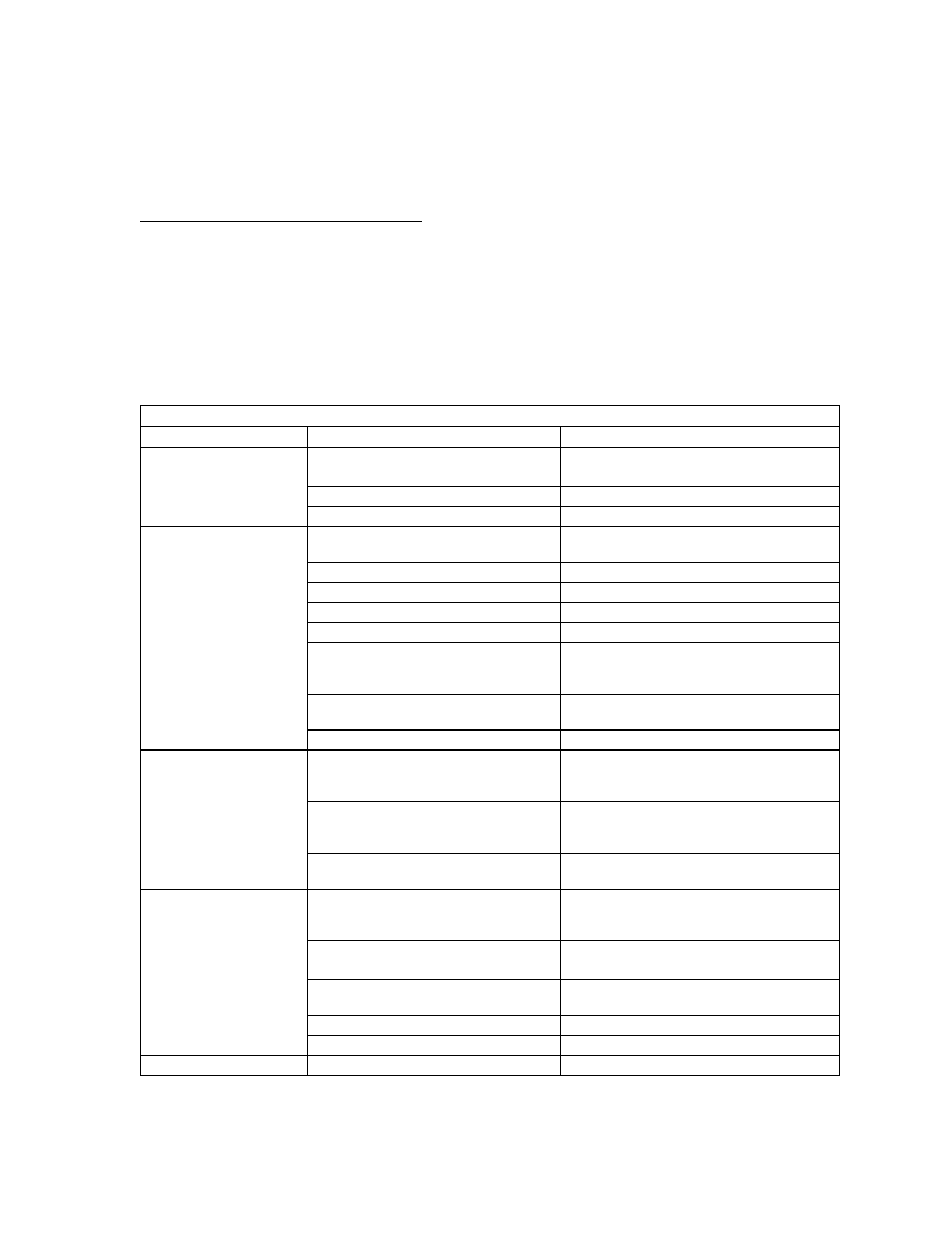
Table 3.7-1 User Diagnostics
Symptom
Check
Further Checks and Corrections
No output and the
display is blank.
Is input voltage within specified
range?
Connect to appropriate voltage source.
See Section 2.5.
Power switch ON?
Turn on power.
Internal circuit?
See your service technician.
No output but the display
turns on.
OVP LED lit?
See Section 3.3.
Front panel S/D LED lit?
See Section 3.4.
OTP LED lit?
See Section 3.6.
Current limit set to zero?
See Section 3.2.
Voltage control set to zero?
See Section 3.2.
REM LED lit?
If using remote analog control, check your
analog programming source (Section 4). If
not, refer to your digital interface manual.
Is front panel ACF LED lit?
Connect unit to AC supply in specified
range. See Section 2.5.
Internal circuit.
See your service technician.
Output not adjustable.
Is unit in current limit mode? (Red
Current Mode LED lit.)
Turn current knob clockwise to increase
current limit. Reduce load if current is at
maximum. See Section 3.2.
Is unit in remote mode? (Green REM
LED lit.)
If using remote analog control, check your
analog programming source (Section 4). If
not, refer to your digital interface manual.
Is unit at maximum voltage or current
limit?
Reduce load for lower voltage or current
requirement.
Output voltage
fluctuating or regulation
poor.
Is unit at current limit?
Increase current limit setting or reduce
load. See Section 3.2.
Is input voltage within specified
range?
Connect to appropriate AC voltage source.
See Section 2.5.
Are sense lines connected?
See Section 2.7 Load Connection and
Section 2.8 Local and Remote Sensing.
Is unit under remote analog control?
Ensure program source is stable.
Internal circuit.
See your service technician.
Output oscillating.
Internal circuit.
See your service technician.