American Magnetics 12100PS DC Power Supply (CE-Marked) User Manual
Page 16
INSTALLATION
OPERATING MANUAL
2-2
Release 2.0 (98/06)
2.3.1
Initial Inspection (continued)
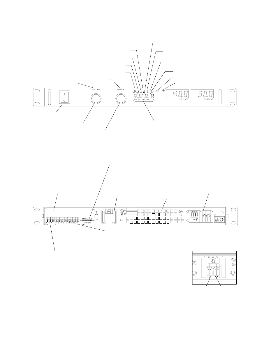
Figure 2.3-1 Power Supply Front Panel
Figure 2.3-2 Power Supply Rear Panel
(Low voltage (7.5V to 40V) model shown.)
Voltage Mode
LED
Current Mode
LED
OVP Adjust Potentiometer (OVP SET)
OVP Shutdown LED (OVP)
OVP Setting Preview Switch (OVP CHECK)
Local Voltage & Current Limit Setting
Preview Switch (V/I CHECK)
Standby Switch (STANDBY)
Shutdown LED (S/D)
Return to Local Programming (LOCAL)
(For units with digital programming
interface installed.)
Remote Programming LED (REM)
Over Temperature Protection LED (OTP)
AC Fail LED (ACF)
Blank Subplate
(Replaced if digital
programming
interface installed.
J10 Sense Connector
(See Section 2.8 for more
information.)
1 Return Sense
2 Negative Output (Return)
3 No connection (N/C)
4 Positive Output
5 Positive Sense
J2 Programming and Monitoring Connector
(See Section 4.2 for more information.)
1 Remote Output Voltage Programming Select
2 Remote Output Current Limit Programming Select
3 Control Ground
4 N/C
5 Voltage Program Signal Return
6 Output Voltage Program Input
7 Current Program Signal Return
8 Output Current Limit Programming Input
9 Voltage Monitor Signal Return
10 Output Voltage Monitor
11 Current Monitor Signal Return
12 Output Current Monitor
13 N/C
14 TTL Shutdown (S/D) Signal Return (-)
15 TTL S/D Input (+)
SW1 Switch (See Section 4.2 for more information.)
1 Resistive Programming of Output Voltage
2 Resistive Programming of Output Current Limit
3 Output Voltage Programming Source Range
4 Output Current Limit Programming Source Range
5 Output Voltage Monitor Range
6 Output Current Monitor Range
7 Remote Shutdown Logic
8 Over Temperature Reset Mode
Fan Exhaust Vents
(Do not obstruct.)
AC Input
Connector
(See Section
2.5
for more
i f
ti
)
AC Power
Switch
Output Voltage Control Knob
Output Current Control Knob
Remote Programming LEDs.
(For units with digital programming interface
installed.)
Positive
Output (+)
Return (-)
Output Voltage Connector
(For high voltage (60V to
600V) models)
DC Output for Bus Bar
Models
(See inset and Section 2.7
for more information.)