American Magnetics 12100PS DC Power Supply (CE-Marked) User Manual
Page 25
OPERATING MANUAL
INSTALLATION
Release 2.0 (98/06)
2-11
2.7.2
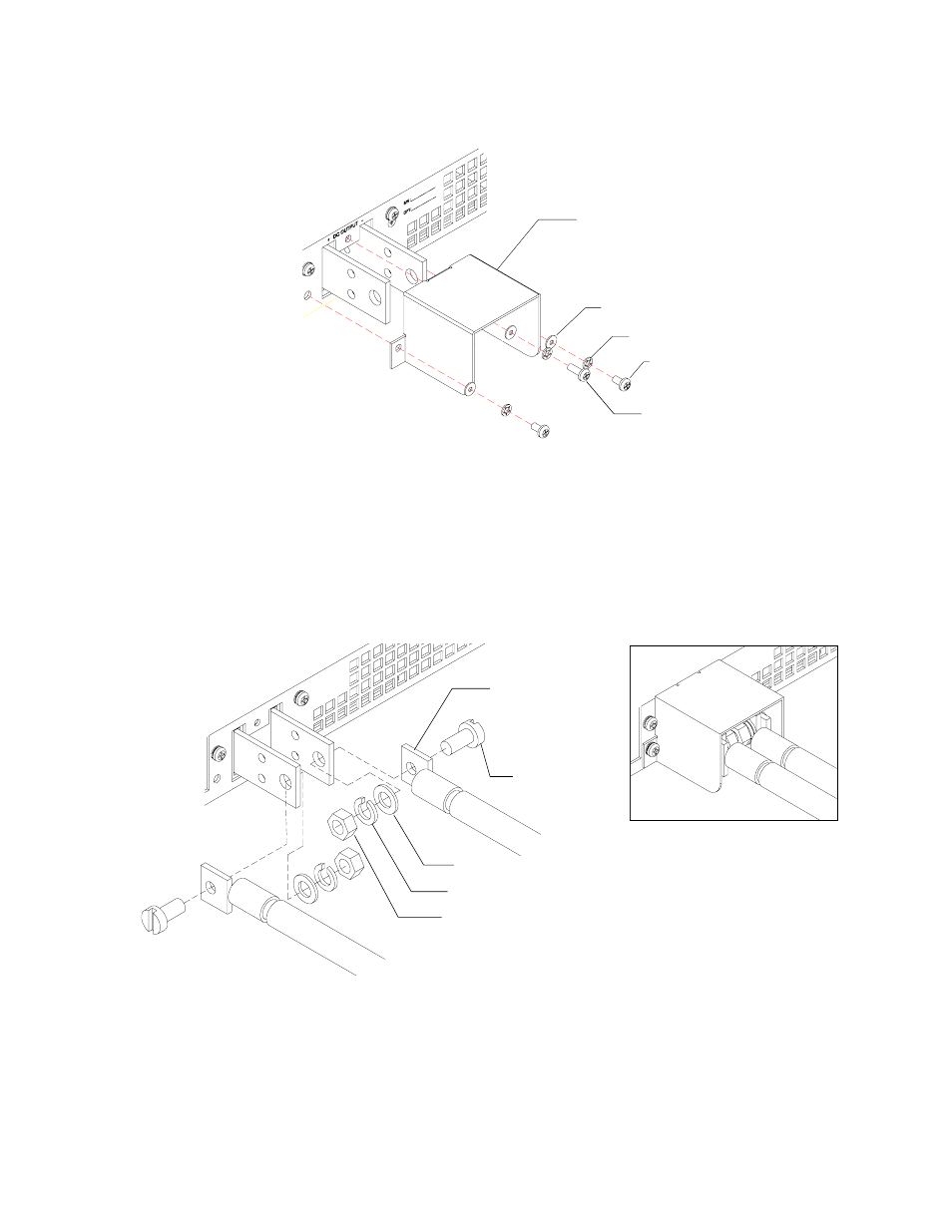
Making Load Connections (continued)
Figure 2.7-2 Bus Bar Shield
To make load connections to a typical 7.5V, 140A power supply:
1. Install connectors such as the Thomas and Betts wire connector #54158 to load wiring.
2. Fasten connectors to bus bars with 5/16" x 5/8" (M8 x 16 mm) screws and 5/16" (M8) flat washers,
lock washers, and hex nuts as shown in Figure 2.7-3.
Note:
Bus bar hole sizes for the low voltage models are: 1 of 0.332" (8.17 mm) D; and 2 of 0.197" (5.0 mm) D.
Figure 2.7-3 Typical Load Connection Hardware
(Low voltage model shown.)
Wire Connector
(2 places)
Screw (2 places)
Hex Nut (2 places)
Lock Washer (2 places)
Flat Washer (2 places)
Shield
Flat Washer (3 places)
Assembled View
Lock Washer (3 places)
1/4" Screw (2 places)
3/8" screw (1
place)
- 12200PS DC Power Supply (CE-Marked) (58 pages)
- MAxes Multi-Axis Magnet systems for Vector Fields (4 pages)
- 05200PS-430-601 High Stability Integrated Power Supply System (226 pages)
- Current Leads for Cryogenic Systems Brochure (8 pages)
- 150A Portable Liquid Helium Level Meter (CE-Marked) (7 pages)
- AMI Liquid Helium Level Sensors (7 pages)
- 187 Self-Compensating Liquid Level Controller (75 pages)
- 286 Multi-Sensor Liquid Level Instrument (CE-Marked) (116 pages)
- 601 Energy Absorber (CE-Marked) (7 pages)
- 05100PS-430-601 Integrated Power Supply System (224 pages)
- 4Q06125PS-430 Integrated Power Supply System (216 pages)
- SVTI-CH6022-2 (2 pages)
- OPMX-141-1 (2 pages)
- 05500PS-430-601 High Stability Integrated Power Supply System (228 pages)
- 188CPS Point-Sensing Instrument (29 pages)
- MX-4.5_9-30 (2 pages)
- 4Q05100PS Four-Quadrant Power Supply (7 pages)
- AMI Superconducting Magnets (25 pages)
- Current Leads for Cryogenic Systems Manual (10 pages)
- SD-6-15 (2 pages)
- CRYOGEN FREE SUPERCONDUCTING MAGNET SYSTEMS (4 pages)
- 4Q06250PS-430 Integrated Power Supply System (216 pages)
- 4Q12125PS-430 Integrated Power Supply System (216 pages)
- 430 Power Supply Programmer (4 pages)
- 110 Liquid Helium Level Meter (CE-Marked) (30 pages)
- 420 Power Supply Programmer (134 pages)
- 175 Industrial Level Transmitter (CE-Marked) (18 pages)
- 05100PS-430-601 High Stability Integrated Power Supply System (226 pages)
- 4Q12125PS-430 High Stability Integrated Power Supply System (216 pages)
- 4Q06125PS-430 High Stability Integrated Power Supply System (216 pages)
- 4Q1005PS-430 Integrated Power Supply System (214 pages)
- 160 Liquid Helium Level Superconducting Dipstick (4 pages)
- 05200PS-430-601 Integrated Power Supply System (224 pages)
- 4Q1010PS-430 Integrated Power Supply System (214 pages)
- 05300PS-430-601 High Stability Integrated Power Supply System (226 pages)
- 4Q06250PS-430 High Stability Integrated Power Supply System (216 pages)
- 185 & 186 Liquid Level Instruments (CE-Marked) (82 pages)
- 03300PS-430-601 High Stability Integrated Power Supply System (226 pages)
- 135 & 136 Liquid Helium Level Instruments (CE-Marked) (72 pages)