American Magnetics 12100PS DC Power Supply (CE-Marked) User Manual
Page 20
INSTALLATION
OPERATING MANUAL
2-6
Release 2.0 (98/06)
2.5.3
AC Input Wire Connection
1. Strip the outside insulation on the AC wire approximately 4" (10 cm). Trim wires so that the ground
wire is 0.5" (12 mm) longer than the other wires. Strip 0.55" (14 mm) at the end of each of the wires.
See Figure 2.5-1, Stripped AC Wire.
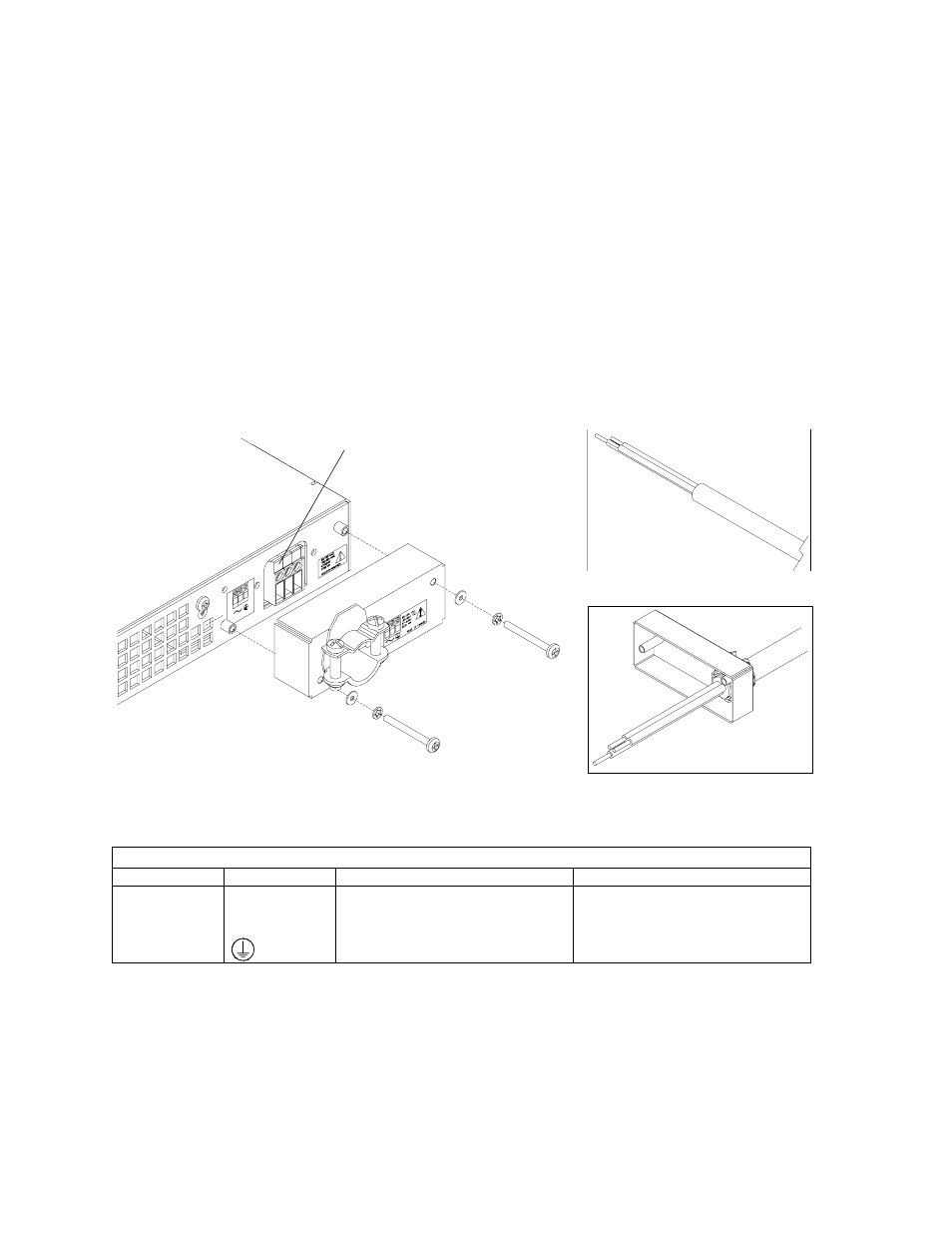
2. Undo the two screws for the AC wiring strain relief/cover on the rear panel. Remove the cover. See
Figure 2.5-1.
3. Loosen the strain relief screws. Insert the AC input cable through the strain relief until the outer cable
jacket is flush with the inside of the strain relief. Tighten the strain relief cable clamp screws. See
Figure 2.5-1, AC Wire Installed in Strain Relief.
4. Route the AC wires to the input connector terminals as required. See Table 2.5-3. To connect the
wiring, loosen the terminal screw, insert the stripped wire 0.55" (14 mm) into the terminal, and tighten
the screw securely.
5. Reinstall the AC input cover, routing wires inside the cover to prevent pinching.
Figure 2.5-1 AC Input Cover and Strain Relief
Table 2.5-3 AC Input Connector Terminals and Connections
Terminal
Label
Connect for 85-130V Operation
Connect for 190-264V Operation
1
~
Neutral wire
Line
2
~
Line
Line
3
Safety Ground
Safety Ground
Stripped AC Wire
AC Wire Installed in Strain Relief
Terminal 1 (See Table 2.5-3.)