American Magnetics 12100PS DC Power Supply (CE-Marked) User Manual
Page 24
INSTALLATION
OPERATING MANUAL
2-10
Release 2.0 (98/06)
2.7.1
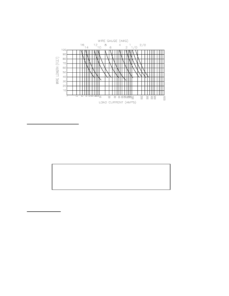
Load Wiring (continued)
Figure 2.7-1 Maximum Load Wire Length for 1V Line Drop
Noise and Impedance Effects
To minimize noise pickup or radiation, use shielded-twisted pair wiring of as short a length as possible for load
wires. Connect the shield to the chassis via a rear panel mounting screw. Where shielding is impossible or
impractical, simply twisting the wires together will offer some noise immunity. When using local sense
connections, use the largest practical wire size to minimize the effects of load line impedance on the regulation
of the supply.
2.7.2
Making Load Connections
CAUTION
When making connections to the bus bars, ensure each terminal's mounting
hardware and wiring assembly are placed to avoid touching the other
terminal and shorting the power supply output. Heavy connecting cables
must have some form of strain relief to avoid loosening the connections or
bending the bus bars.
Make load connections at the rear of the power supply at the positive and negative output bus bars or to the
4-terminal wire clamp connector, depending on the model.
7.5V to 40V Models
The 7.5V to 40V models have output bus bars and may come with a bus bar shield in some configurations. To
detach the shield before connecting load wires, remove 6-32 x 1/4" screws (2), 6-32 x 3/8" screw (1), and lock
washers and flat washers (3 places). See Figure 2.7-2.