Bosch GPL 3 Professional User Manual
Page 11
English | 11
Bosch Power Tools
1 609 929 S08 | (13.3.12)
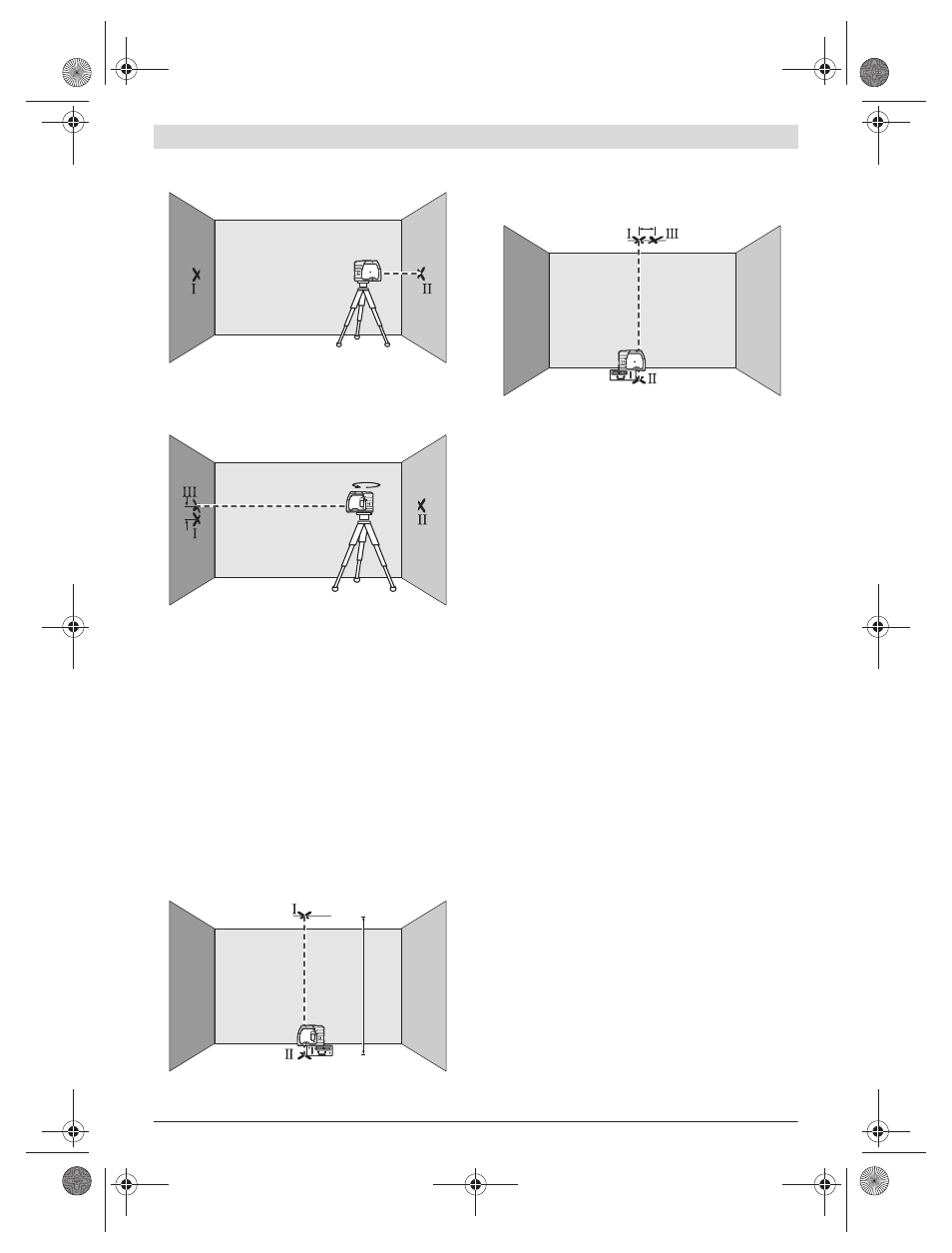
– Without turning the measuring tool, position it close to wall
B. Switch the measuring tool on and allow it to level in.
– Align the height of the measuring tool (using the tripod or
by underlaying, if required) in such a manner that the cen-
tre point of the laser beam is projected exactly against the
previously marked point II on wall B.
– Rotate the measuring tool by 180° without changing the
height. Allow it to level in and mark the centre point of the
laser beam on wall A (point III). Take care that point III is
as vertical as possible above or below point I.
– The difference d of both marked points I and III on wall A
indicates the actual height deviation of the measuring tool.
On the measuring distance of 2 x 20 m = 40 m, the maximum
allowable deviation is: 40 m x ±0.3 mm/m = ±12 mm.
Thus, the difference d between points I and III may not ex-
ceed 12 mm (max.).
Checking the Vertical Levelling Accuracy
For this check, a free measuring distance of approx. 5 m be-
tween floor and ceiling on a firm surface is required.
– Draw a straight line on the ceiling.
– Mount the measuring tool to the holder or a tripod. Switch
the measuring tool on and rotate it in such a manner that
the bottom plumb beam can be seen on the floor.
– Position the measuring tool in such a manner that the up-
per plumb beam points against the line on the ceiling. Al-
low the measuring tool to level in. Mark the centre of the
upper laser point on the line on the ceiling (point I). Also,
mark the centre of the laser point on the floor (point II).
– Rotate the measuring tool by 180°. Position it in such a
manner that the centre of the bottom laser point is direct-
ed on the already marked point II and the upper laser point
is directed against the line on the ceiling. Allow the meas-
uring tool to level in. Mark the centre of the upper laser
point on the line on the ceiling (point III).
– The difference d of both marked points I and III on the ceil-
ing results in the actual deviation of the measuring tool to
the plumb line.
On the measuring distance of 2 x 5 m = 10 m, the maximum
allowable deviation is:
10 m x ±0.3 mm/m = ±3 mm.
Thus, the difference d between points I and III must not
exceed 3 mm (max.).
Working Advice
f
Always use the centre of the laser point for marking.
The size of the laser point changes with the distance.
Attaching with the Holder
To fasten the measuring tool on the holder 8, screw the lock-
ing screw 9 of the holder into the 1/4" tripod mount 6 on the
measuring tool and tighten. To rotate the measuring tool on
the holder, slightly loosen the screw 9.
– Rotate the measuring tool on the holder 8 sideward or to-
ward the rear to make the bottom plumb beam visible.
– Rotate the measuring tool on the holder 8 to project
heights with the horizontal laser beam.
With the holder 8, the measuring tool can be attached as
follows:
– Mount the holder 8 to the tripod 18 or a commercially
available camera tripod via the 1/4" tripod mount 13. For
fastening to a commercially available construction tripod,
use the 5/8" tripod mount 14.
– The holder 8 can be fastened to steel parts via the magnets
12.
– The holder 8 can be fastened to drywalls or wood walls
with screws. For this, insert screws with a minimum length
of 60 mm into the screw holes 10 of the holder.
– The holder 8 can also be fastened to pipes or similar beams
using a commercially available strap by threading it
through the opening 11 for strap attachment.
A
B
d
180˚
A
B
5 m
d
OBJ_BUCH-807-003.book Page 11 Tuesday, March 13, 2012 9:26 AM