Connecting an external signal – Acroprint ATR440 Payroll Recorder User Manual
Page 29
29
5. Connecting an external signal
External signals will be activated at the times programmed in section
3.10, Setting Signals. If external signal(s) are required, the addition of
a relay (not supplied) will be necessary. Please consult your local
electrician.
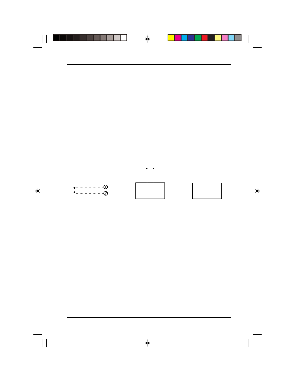
On the back rear of the ATR 440 is a door to access the internal relay
contacts. When the access door is removed, you will see two terminal
screws. The screws are for low voltage (Class 2) contacts for the
internal relay. At programmed signal time, the internal contacts close
completing the circuit. The relay contacts are "dry" and supply no
voltage. Voltage applied to these contacts must not exceed 30 Volts.
An external relay must be used in order to activate signaling devices.
Please note that the external relay is not supplied or offered by
Acroprint.
Connecting an external signal
Replacing the fuse
1) Remove the front and rear covers (see Section 7).
2) There are two fuses on the front board and one fuse on the rear
board in black holders marked "FUSE 5X20".
3) Note: Both the front and rear circuit boards each have a fuse
marked F1. On the front board, one fuse is marked .5A, the other
is marked 1A. The F1 or .5A fuse is for the AC power supply. It's
for everything except the signal control. The F2 or 1A fuse is
dedicated to the signal control line. The fuse on the rear board, F1,
is a 2.5 Amp fuse for the signal control.
4) Pull the fuse holder from the board. Remove the fuse from its
holder and check to see if it is burned out.
5) Replace the burned out fuse and snap it back into its holder.
6) Place the fuse holder back onto the board.
7) Reinstall the front and rear covers.
External
Relay
Signal Input
Voltage 125 VAC
External
Signal
30 Volts
(Class 2)
125 VAC
ATR 440
Internal
Relay
atr440 A5 paper size.p65
8/21/02, 8:16 AM
29