Figure 9 - unit dimensions dhg unit, Table 20: clearances, 9 unit dimensions dhg unit – York D2HE/D2HG060 User Manual
Page 19: 20 clearances
036-21216-003-A-0204
Unitary Products Group
19
NOTE: DHG modes must be provided a 1” clearance
between any combustible material and the supply
air ductwork for a distance of 2 feet from the unit.
The products of combustion must not be allowed to accumu-
late with a confined space and recirculate. Locate unit so that
the vent air outlet hood is at least.
•
Three feet above any forced air inlet located within 10
horizontal feet (excluding those integral to the unit).
•
Four feet below, 4 horizontal feet from, or 1 foot above
any door or gravity air inlet into the building.
•
Four feet from electric meters, gas meters, regulators
and relief equipment.
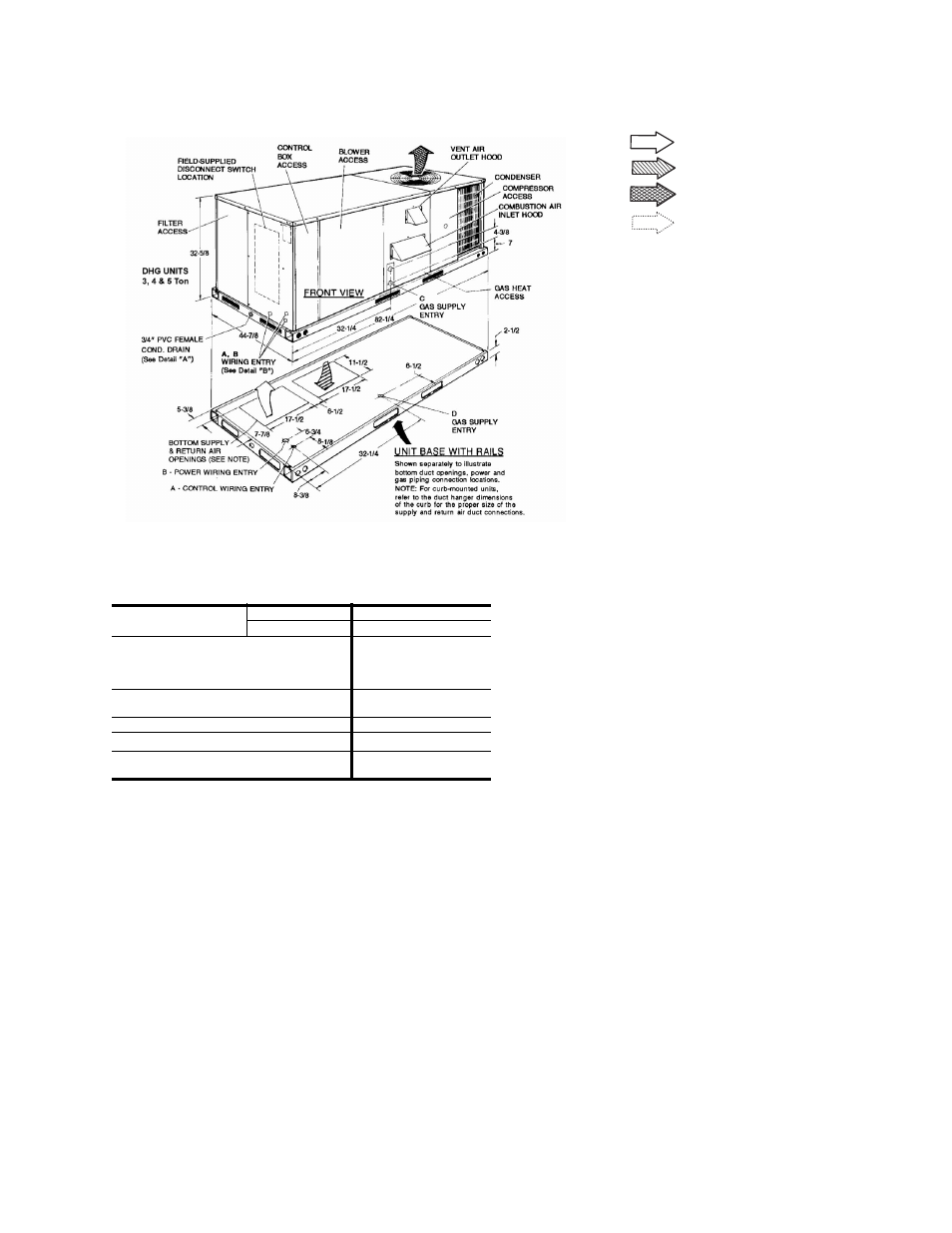
FIGURE 9 - UNIT DIMENSIONS DHG UNIT
TABLE 20: CLEARANCES
FRONT
DHE UNITS
24”
DHG UNITS
32”
BACK
12” (Less Economizer)
36” (With Economizer or
Fixed Air/Motorized
Damper)
LEFT SIDE (Filter Access)
24” (Less Economizer)
36” (With Economizer)
RIGHT SIDE (Cond. Coil)
24”
BELOW UNIT
1
1.
Units may be installed on combustible floors made from
wood or class A, B, or C roof covering material.
0”
ABOVE UNIT
2
2.
Units must be installed outdoors. Overhanging struc-
tures or shrubs should not obstruct condenser air dis-
charge outlet.
72” (For Condenser Air
Discharge)
R E T U R N A I R
S U P P L Y A I R
O U T D O O R A I R
O U T D O O R A I R
( E c o n o m i z e r )
All dimensions are in inches. They are
subject to change without notice. Certi-
fied dimensions will be provided upon
request.