Wayne-Dalton 9800 User Manual
Page 14
Tools Needed:
Please Do Not Return This Product To The Store. Contact your local Wayne-Dalton dealer.
To find your Wayne-Dalton dealer; refer to your local yellow pages / business listings or go to Find a dealer area online at
www.wayne-dalton.com
14
Tools Needed:
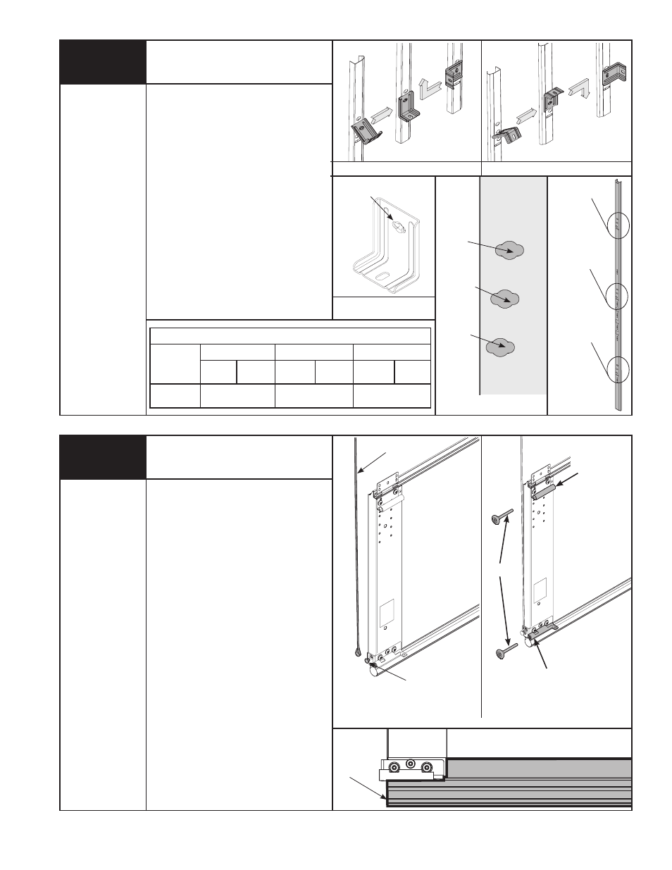
Counterbalance Cables
None
bOTTOM
sECTION
asTRaGEl
6
IMPORTANT: RIGhT aND lEFT haND
Is alWays DETERMINED FROM INsIDE
ThE buIlDING lOOkING OuT.
NOTE: For door section identification
see page 4.
uncoil the counterbalance cables and
slip the loop at the ends of the cables
over the milford pins on the bottom
section. Insert a short shaft roller in the
bottom bracket on the bottom section
and another short shaft roller in the
#1 end hinge at the top of the bottom
section. Repeat for other side.
NOTE: Verify astragal (bottom seal)
is aligned with door section. If there
is more than 1/2” excess astragal on
either side, trim astragal even with door
section.
bOTTOM sECTION
MIlFORD PIN
ROllERs
#1 END hINGE
(hINGE TubE)
bOTTOM bRaCkET
bOTTOM sECTION
COuNTERbalaNCE
CablE
quICk INsTall FEaTuRE
None
5
Installing q.I. Jamb Brackets
TOP
hOlE
bOTTOM
hOlE
MIDDlE
hOlE
3RD sET hOlEs
2ND sET hOlEs
1sT sET hOlEs
qI jaMb bRaCkET
TWIsTlOCk Tab
lEFT sIDE shOWN
RIGhT sIDE shOWN
NOTE: If you have fully adjustable jamb
brackets, skip this step and complete
step 6.
Measure the length of the vertical
tracks. using the jamb bracket schedule,
determine the placement of the jamb
brackets for your door height and track
type. To install the jamb brackets, align
the twistlock tab on the quick install
jamb bracket with the quick install
feature in the track and turn the bracket
perpendicular to the track so the
mounting flange is toward the back (flat)
leg of the track.
NOTE: after completing this step,
continue with step 6.
JAMB BRACkET SChEDULE
DOOR
hEIGhT
1ST SET
2ND SET
3RD SET
JAMB
BkT
POS.
JAMB
BkT
POS.
JAMB
BkT
POS.
6’6” - 7’0”
TRACk
qIjb - 3
MIDDlE
qIjb - 5
bOTTOM
NOT aPPlICablE