Warning – Wayne-Dalton 8000 SERIES 46 User Manual
Page 34
34
Please Do Not Return This Product To The Store. Contact your local Wayne-Dalton dealer. To find your local Wayne-Dalton dealer, refer to your
local yellow pages/business listings or go to the
Find a Dealer section online at www.wayne-dalton.com
Tools Needed:
Tools Needed:
�
�
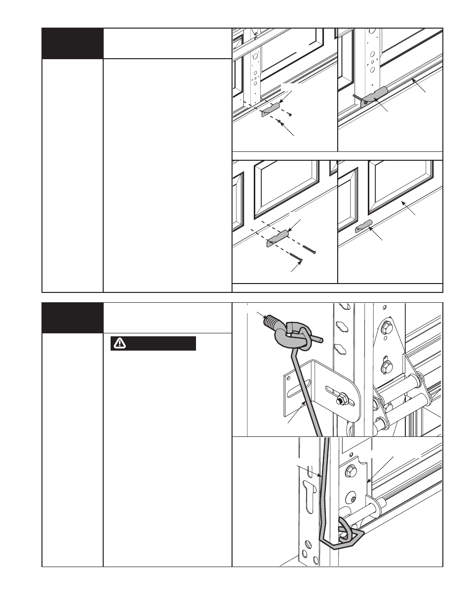
Pull Rope
NO. 6 SCREW EyE
PuLL ROPE
BOTTOM BRACkET
PuLL ROPE
DO NOT INSTALL PuLL ROPES
ON DOORS WITh ELECTRIC
OPERATORS. ChILDREN MAy
BECOME ENTANGLED IN ThE
ROPE CAuSING SEVERE OR
fATAL INjuRy.
Measure and mark the jamb
approximately 48” to 50” (1220 to 1270
mm) from floor on the right or left side
of door. Drill 1/8” pilot hole for No. 6
screw eye. Tie the pull rope to the No.
6 screw eye and to the bottom bracket
as shown.
wARNINg
Power Drill
Drill Bit
STEP PLATE
Step Plate
Locate the center stile on the bottom
section of the door.
On the outside of the door, position step
plate directly above astragal retainer.
using the step plate as a template,
mark hole locations for mounting on
door face.
Drill (2) 5/16” dia. holes through the
door face and insulation, if necessary, at
marked locations, being careful to keep
drill straight.
Mount step plates back to back,
straddling stile. Secure with
(2) 1/4 x 2-3/4” carriage bolts and 1/4”-
20 flange hex nuts.
NOTE: After completing this step,
continue with Step 13 on page 18.
INSIDE STEP PLATE INSTALLATION
OuTSIDE STEP PLATE INSTALLATION
(2) 1/4”-20 fLANGE hEx NuT
(2) 1/4 x 2-3/4”
CARRIAGE BOLTS
STEP PLATE
STEP PLATE
ASSEMBLy
STEP PLATE ASSEMBLy
BOTTOM SECTION
BOTTOM
SECTION
BOTTOM
SECTION
BOTTOM
SECTION
Pencil
1/4” Wrench