Wayne-Dalton 8000 SERIES 46 User Manual
Page 17
17
Please Do Not Return This Product To The Store. Contact your local Wayne-Dalton dealer. To find your local Wayne-Dalton dealer, refer to your
local yellow pages/business listings or go to the
Find a Dealer section online at www.wayne-dalton.com
Tools Needed:
Tools Needed:
INST
All
ATION
10
bottom Section
9
Before installing the bottom section,
the weather seal (may not be included)
must be installed (see PREPARING ThE
OPENING on page 10)
Center the bottom section in the door
opening. Level section using wooden
shims under the bottom astragal if
necessary. hold the section in the
opening while attaching vertical tracks.
WEAThER
SEAL
LEVEL
hEADER
Level
Wood Shims
jAMB
BOTTOM
SECTION
WOODEN
ShIMS
jAMB
Tape Measure
Pencil
Power Drill
9/32” Drill Bit
1/2” Drill Bit
1/4” Wrench
lift handle
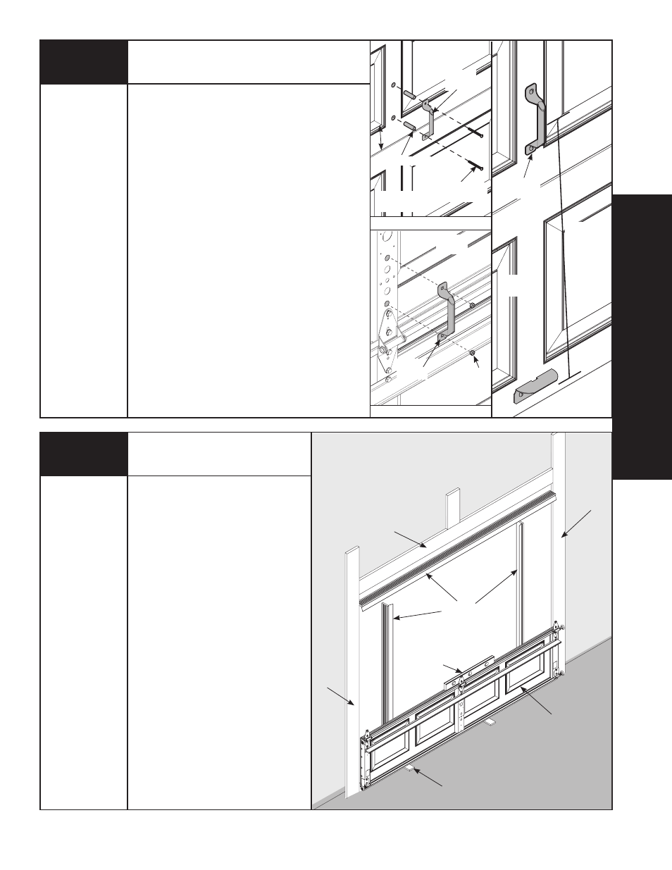
NOTE: Doors with a keyed lock do not require this lift
handle.
NOTE: for door section identification see page 4.
Locate the inside center stile or the desired lift handle
location on the lock (2nd) section of the door. Position
the lower hole in the lift handle 4” from the bottom of
the second section.
IMPORTANT: The distance between the step/lift
plate and the middle of the lift handle must be 20”
minimum to 30” maximum. If needed reposition upper
lift handle to stay within the required dimension.
Drill (2) 9/32” dia. holes through section. Enlarge the
holes from outside the door to 1/2” dia.
Assemble the outside and inside lift handle to the
section using (2) 1/4” x 2-1/2” carriage bolts,
( 2) 1/4”- 20 hex nuts and (2) spacers.
NOTE: Do not drill through or enlarge holes on the
inside of the door.
LIfT hANDLE OuTSIDE
LIfT hANDLE INSIDE
LOCk
SECTION
LOCk
SECTION
LOCk
SECTION
BOTTOM
SECTION
BOTTOM
SECTION
BOTTOM SECTION
LIfT
hANDLE
LIfT
hANDLE
LIfT
hANDLE
(2) SPACERS
(2) 1/4”-20
hEx NuT
(2) 1/4” x 2-1/2”
CARRIAGE BOLTS
4”
20” TO 30”