VXI 3002 User Manual
Page 92
5-17
0 Hz (DC)
To measure the AM depth at DC, it will be necessary to use the DC offset facility on the function
generator proceeding as follows:
6960B
RF power meter
6912
Power
sensor
C2566
OUTPUT
Temporary
connection
SENSOR
INPUT
Function generator
DVM
RF
OUT
50
load
Ω
UUT
EXT MOD
INPUT
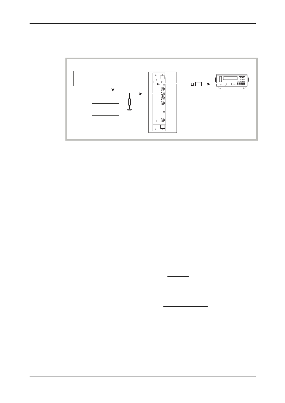
Fig. 5-9 0 Hz external AM and distortion test set-up
(9) Connect the test equipment as shown in Fig. 5-9.
(10) Set the function generator to +1.4142 V DC (temporarily connect the function generator
output to the DVM and set this voltage as close as possible to +1.4142 V).
(11) Measure the power on the power meter.
P1 _____
(12) Set the function generator to
−1.4142 V DC (temporarily connect the function generator
output to the DVM and set this voltage as close as possible to
−1.4142 V).
(13) Measure the power on the power meter.
P2 _____
(14) Subtract P2 from P1 (= x).
(15) Calculate the modulation depth using the formula:
пю
п
э
ь
по
п
н
м
(-x/20)
(-x/20)
10
+
1
10
-
1
=
AM(%)
(16) Calculate the 0 Hz response relative to 1 kHz using the following formula, recording the
result in Table 5-35:
ю
э
ь
о
н
м
)
15
(
in
recorded
Figure
)
6
(
in
recorded
Figure
log
20
10
(17) Set the UUT RF level to +7 dBm and repeat (10) to (16) using Table 5-36.
(18) Set the UUT RF level to +13 dBm and repeat (10) to (16) using Table 5-37.