Pulse modulation rf level frequency response, Test procedure, Pulse modulation on/off ratio – VXI 3002 User Manual
Page 128
Annex-A-2
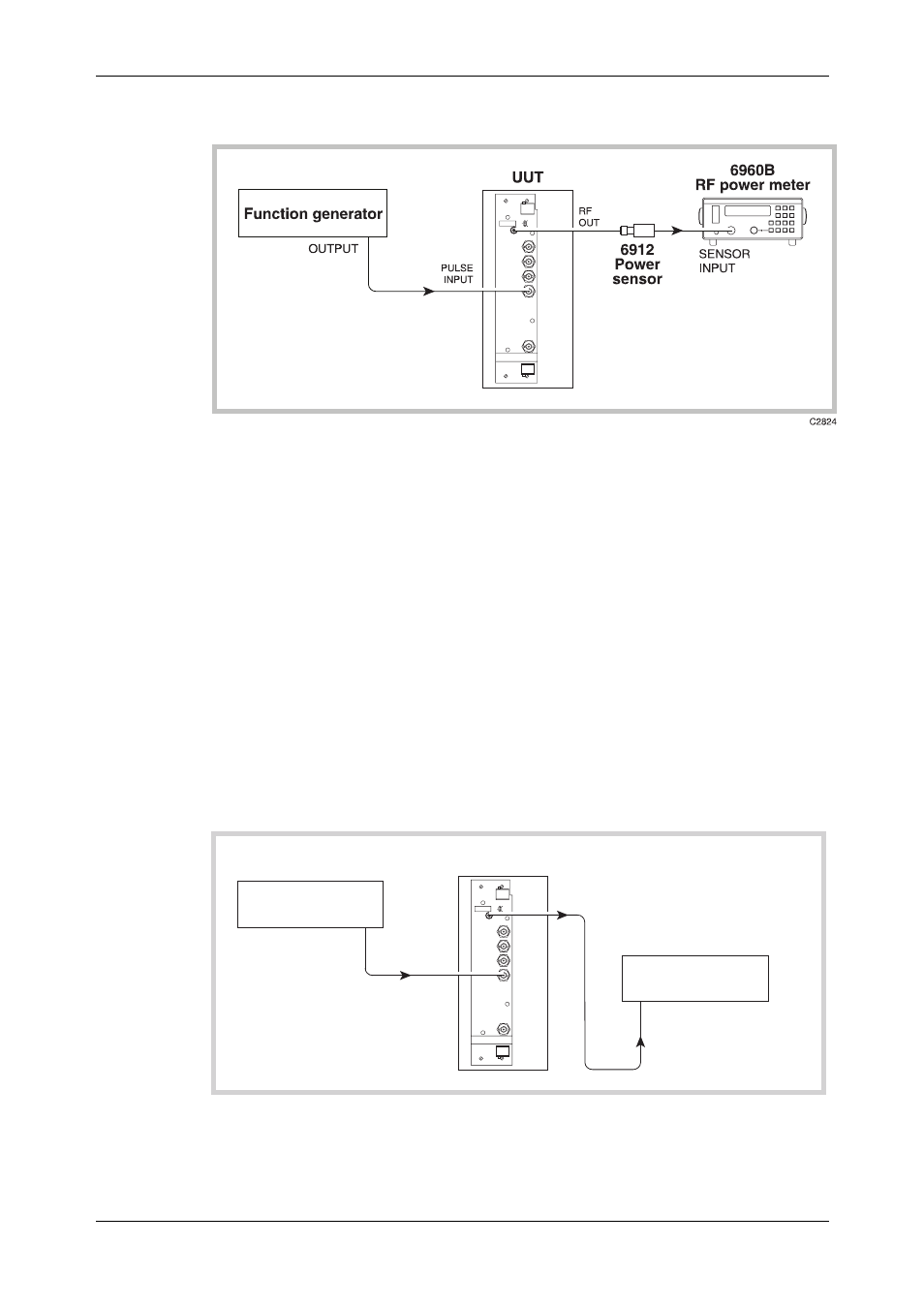
Pulse modulation RF level frequency response
Fig. A-1 Pulse modulation test set-up
Test procedure
(1)
Perform AUTO ZERO and AUTO CAL on the power meter.
(2)
Connect the test equipment as shown in Fig. A-1.
(3)
On the UUT set:
Carr Freq
100 kHz
RF
Level
−7 dBm
Pulse
ON
(4)
Set the function generator to provide +5 V DC. The RF output will now be enabled.
(5)
Record the output level measured by the power meter against each of the carrier frequencies
shown in Table A-1, checking that the results are within specification.
(6)
Set the UUT RF level to +0 dBm and repeat (5) using Table A-2.
(7)
Set the UUT RF level to +16 dBm and repeat (5) using Table A-3.
Pulse modulation on/off ratio
C5358
OUTPUT
Function generator
RF
OUT
UUT
PULSE
INPUT
RF INPUT
Spectrum analyzer
Fig. A-2 Pulse modulation on/off ratio test set-up