Carrier error – VXI 3002 User Manual
Page 87
5-12
Carrier error
Test procedure
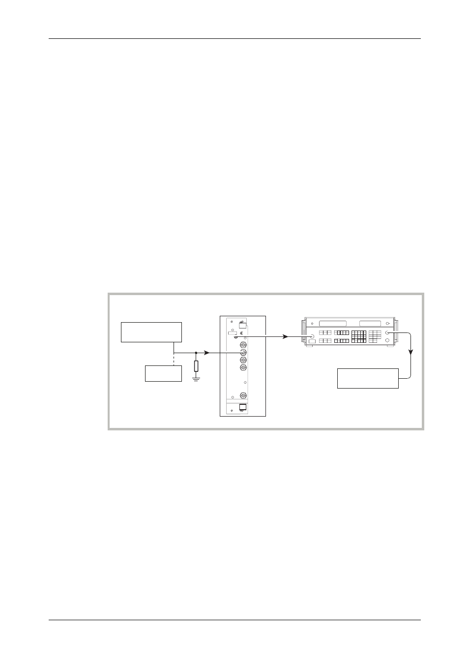
(1) Connect the test equipment as shown in Fig. 5-7.
(2) On the UUT set:
Carr Freq
1200 MHz
RF Level
0 dBm
(3) On the modulation meter select CARRIER ERROR. The FREQUENCY display will read
0.00 kHz.
(4) On the UUT set:
Mod Mode
FM External
FM1 Level
100 kHz
Source
On
Mod
On
DC
coupling
Null
DCFM
(5) On the modulation meter measure the carrier frequency error displayed in the FREQUENCY
window checking that the result is within the specification shown in Table 5-24.
External FM frequency response (ALC off, DC coupled)
Test procedure
2305
Modulation meter
C2565
RF
OUT
OUTPUT
Temporary
connection
RF
INPUT
LF
OUTPUT
INPUT
Function generator
DVM
50
load
Ω
Audio analyzer
UUT
EXT MOD
INPUT
Fig. 5-8 External modulation and modulation distortion test set-up
30 Hz to 100 kHz
(1) Connect the test equipment as shown in Fig. 5-8.
(2) On the UUT set:
Carr Freq
15 MHz
RF Level
0 dBm
Mod Mode
FM External
FM1 Level
50 kHz
Source
On
Mod
On
DC
coupling
(3) Set the function generator to give 1V RMS, 1 kHz sine wave.
(4) On the modulation meter select CAL, FM, 10 Hz
Þ 300 kHz filter.