3 installation, 1 mounting the tank gate interface, 2 select the unit address – Varec TankGate Interface 8315 Series User Manual
Page 72: 3 wiring up power, Closed open
Installation
Tank Gate Interface
62
Installation and Operations Manual
6.3
Installation
Standard systems are shipped with the motherboard and tank gauge interface module installed.
The Tank Gate Interface installation procedure includes the installation of these individual
components. Tank Gate Interface installation includes the following steps:
1. Mounting the Tank Gate Interface (section 6.3.1 on page 62)
2. Selecting the Unit Address (section 6.3.2 on page 62)
3. Wiring up Power (section 6.3.3 on page 62)
4. Grounding the Tank Gate Interface (section 6.3.4 on page 64)
5. Installing Communications (section 6.3.5 on page 64)
6.3.1
Mounting the Tank Gate Interface
Before mounting the Tank Gate Interface, make certain that any enclosure used can house the
Tank Gate Interface. Refer to the dimensional drawing below (all dimensions are in inches). The
recommended standard housing for the Tank Gate Interface is a NEMA TYPE 4 enclosure. This
enclosure is suitable for both indoor and outdoor applications.
6.3.2
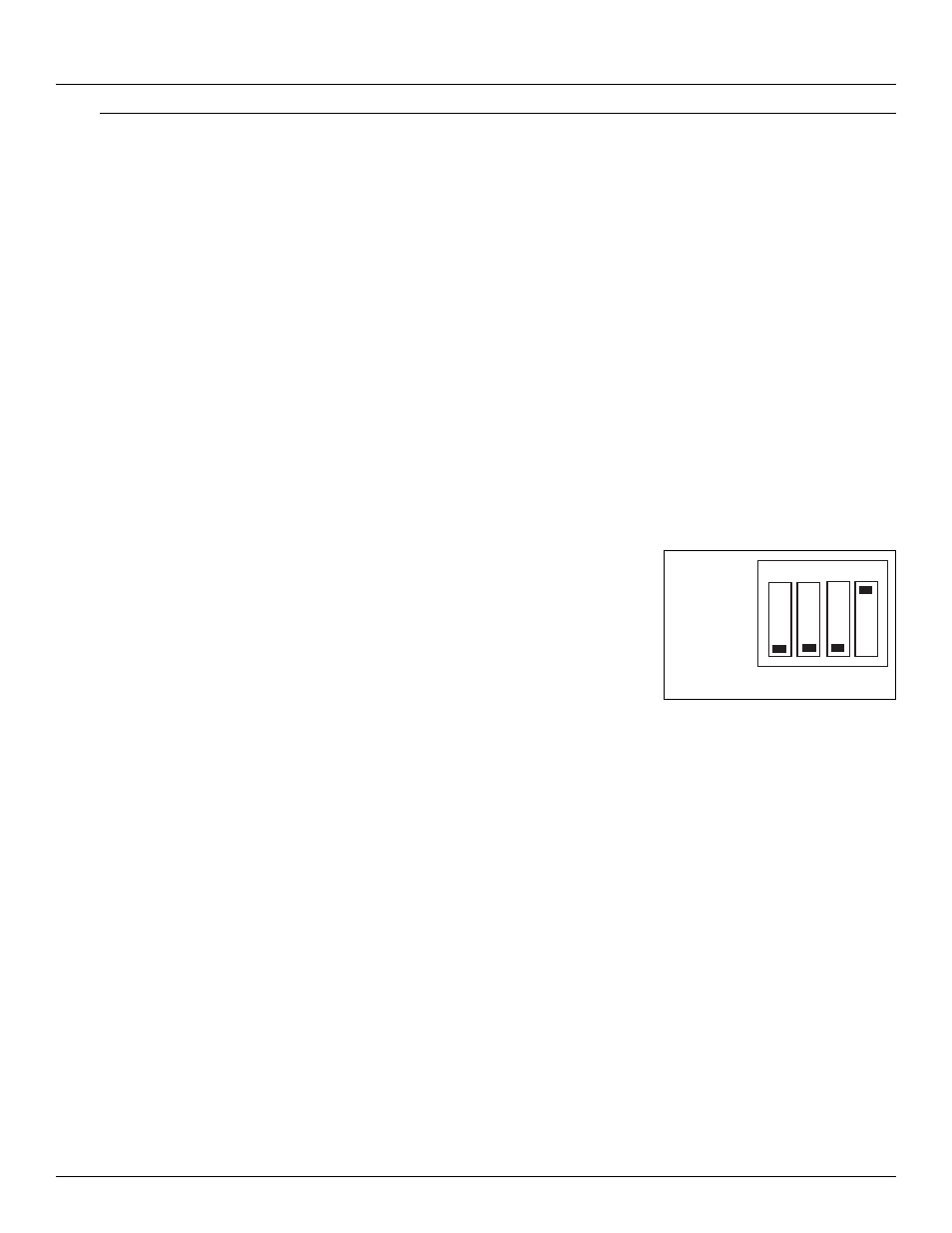
Select the Unit Address
Switch SW1 sets the Tank Gate Interface’s one byte, binary
address (0-15). Switch SW1-1 is the most significant bit
(MSB) while switch SW1-4 is the least significant bit (LSB).
When a switch is in the ON or CLOSED position, the resulting
bit is a one.
Figure 6-1: Switch SW-1 setting for ID 1
6.3.3
Wiring Up Power
The Tank Gate Interface operates from AC power.
Wiring 120 or 220 VAC Power
The Tank Gate Interface is powered by an isolation transformer with a 5 volt regulator.
•
Remove cover if it is in place
•
Connect the two power leads to terminals L and N of connector J2.
•
Ensure that a ground connection is connected to the G terminal ground of connector J2. (see
below)
•
Install cover.
Address 1 Shown
CLOSED
OPEN
1
2
3
4