3 maintenance – Varec TankGate Interface 8315 Series User Manual
Page 104
Troubleshooting
Tank Gate Interface
94
Installation and Operations Manual
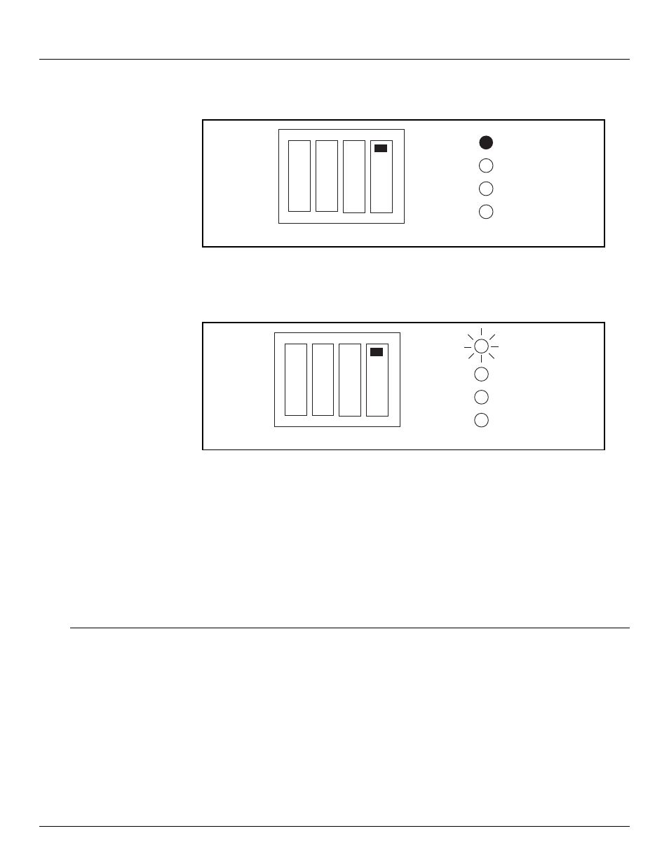
5. The LEDs will light (and remain steady) to indicate the address. For example, if the ID DIP
Switch is set to 1, LEDS D1 will on. If the ID DIP Switch is set to 3, LEDS D1 and D2 will be on.
Figure 8-4: Address indication from the LEDs
6. After 10 seconds, the address of the Tank Gate Interface will be set to the ID DIP Switch
setting. The LEDS will flash for 5 seconds to indicate that the address is about to be set.
Figure 8-5: Set the ID addresses
7. After the address is set, the Tank Gate Interface will begin normal operation with a blank
database:
•
CPU LED: Flashing once per second
•
COM LED: Toggles when communicating to PC
•
TXD: Off when there is no database. When tank gauges are being scanned, the TXD LED will
flash
•
RXD: Off when there is no database. When tank gauges are being scanned, the RXD LED will
flash when a response is received.
8.3
Maintenance
Field maintenance of the Tank Gate Interface is simplified by several built-in features. The
modular design of the computer control system, in conjunction with quick-disconnect
connectors, allows for on-site replacement of questionable components.
The following standard procedure can be used for repairing the Tank Gate Interface:
Replacing a defective component or module
•
Turn off main power.
•
Open the enclosure door. Remove the case cover of the Tank Gate Interface.
•
Replace the defective component or module using the instruction supplied with the spare
part.
ID = 1
D1
D2
D3
D4
ON
ID = 1
D1
D2
D3
D4
FLASHES